
Owner`s manual


DV450S DIRECT VENT ROOM HEATER
01-01 Page 13 29863C
WARNING!
THIS APPLIANCE MAY ONLY USE THE APPROVED
VENTING SYSTEMS SHOWN IN THESE
INSTALLATION INSTRUCTIONS. IT MUST NOT BE
CONNECTED TO CHIMNEY FLUE SERVICING A
SEPARATE SOLID FUEL OR GAS FUEL BURNING
APPLIANCE.
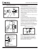
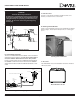
H (MIN.)-MINIMUM HEIGHT
FROM ROOF TO LOWEST
DISCHARGE OPENING
ROOF PITCH IS X/12
LISTED
CAP
LOWEST
DISCHARGE
OPENING
12
X
2 Ft.
Min.
2 Ft. Min.
VERTICAL WALL
HORIZONTAL OVERHANG
Roof Pitch H (min.) ft.
flat to 6/12 1.0
6/12 to 7/12 1.25
over 7/12 to 8/12 1.5
over 8/12 to 9/12 2.0
over 9/12 to 10/12 2.5
over 10/12 to 11/12 3.25
over 11/12 to 12/12 4.0
over 12/12 to 14/12 5.0
over 14/12 to 16/12 6.0
over 16/12 to 18/12 7.0
over 18/12 to 20/12 7.5
over 20/12 to 21/12 8.0
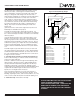
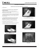
The Dura-Vent GS is unitized and twist-locks together. For the
twist-lock procedure, consult Figure 5 and do the following:
(1) Four indentations, located on the female ends of pipes and
fittings, are designed to slide straight onto the male ends of
adjacent pipes and fittings, by orienting the four pipe indentations
so they match and slide into the four entry slots on the male
ends. (Figure 5.) Push the pipe sections completely together,
then twist-lock one section clockwise approximately one-quarter
turn, until the two sections are fully locked. The female locking
lugs will not be visible from the outside, on the Black Pipe or
fittings. They may be located by examining the inside of the
female ends.
(2) Horizontal runs of vent must be supported every three feet.
Wall Straps are available for this purpose.
Assemble the desired lengths of black pipe and elbows. It is
necessary to reach from the Heater up through the round support
box. Ensure that all pipe and elbow connections are in their fully
twist lock position.
Using the mark from Step 2, drive a nail up through the roof to
mark the center. Measure to either side of the nail and mark
the opening required. This is measured on the horizontal; actual
length may be larger depending on the pitch of the roof. Cut out
and frame the opening. See chapter 25 of the Uniform Building
Code for Roof Framing details. A one inch minimum air space
clearance must be maintained between the vent system and the
roof.
Assemble lengths of pipe and elbows necessary to reach from
the ceiling support box up through the roof line. Galvanized pipe
and elbows may be utilized in the attic, as well as above the roof
line. The galvanized finish is desirable above the roof line due to
its higher corrosion resistance.
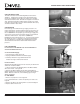
4. Installing the Roof Flashing or Site-Produced Chase Top.
Position a Roof Flashing (or construct a Chase and Chase Top)
and secure in place with nails.
Continue to add Vent sections through the Roof Opening, main-
taining at least 1” Air Space clearance. Major Building Codes
specify a minimum Vent (Chimney) height above the Roof top
depending on Roof Pitch. See Figure 10. Add Pipe sections
until the height of the Vent Cap meets the minimum Building Code
requirements described in Figure 10. Note that for steep roof
Pptches, the vent height must be increased.
These Vent System heights are necessary in the interest of
safety, however, they do not ensure draft-free operation. Trees,
buildings, adjoining Roof lines, adverse wind conditions, etc., may
create a ned for a taller Vent System should down drafting occur.
5. Termination Cap. Twist lock the Vent Cap.
Figure 10 -Vent (Chimney) Height