
User Guide

8
.885 in ± .0236
(22.4 mm ± 0.6)
.055 in ± .0236
(1.4 mm ± 0.6)
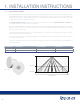
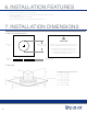
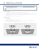
6. INSTALLATION FEATURES
7. INSTALLATION DIMENSIONS
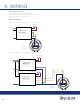
• Mounts into a standard 1/2” electrical knockout
• Push-in connection terminals for #20-#26 AWG solid Copper (twist to remove)
• Silicon retention ring
• Out-of-Box functionality (see section #4)
• Push bezel and hold for 10 seconds to implement factory reset
CAUTION
DO NOT enclose the lower housing in metal, the
antenna is embedded in the face of the product.
Mounting location on the fixture must take into
consideration line of sight installation in the
ceiling grid. Anything that prevents line of sight is
likely to reduce Bluetooth range.
7.1 Knock-out Dimensions
7.1 Spacing
Minimum Spacing Requirements:
A = 0.85 in (21.5 mm)
B = 1.18 in (30.0 mm)
C = 1.41 in (35.9 mm)
D = 0.24 in (6.0 mm)
E = 1.38 in (35.0 mm)
F = 0.09 in (2.4 mm)
M = 0.055 in (1.4mm)
Knock-out
Size
Material
Thickness
!