
Owner's manual
Page 3 of 12
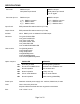
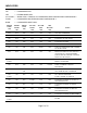
SPECIFICATIONS
Connector: DMX512 Input:
Gold plated 5 pin Neutrik
DMX512 Output:
Gold plated 5 pin Neutrik
on 18" pigtail
Connector pin out: DMX512 Input DMX512 Output
1 (C) DMX512 common 1 (C) DMX512 common
2 ( -) DMX512 data - 2 ( -) DMX512 data -
3 (+) DMX512 data + 3 (+) DMX512 data +
Input Circuit: ESD protected EIA-485 transceiver (LT1785)
Output Circuit: ESD protected EIA-485 transceiver (LT1785)
Isolation: None. DMX input is not isolated from DMX output.
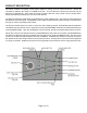
Indicators: Ten green SHOW LEDs
One green PAUSE LED
One green LOOP LED
One yellow START LED
One yellow END LED
One red INPUT/RECORD LED
User controls: Ten [SHOW] buttons
One [PAUSE] button
One [LOOP] button
One [REWIND] button
One [FORWARD] button
One recessed [RECORD] button
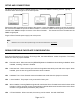
Option Jumpers:
INSTALLED REMOVED
JP1
Recording enabled Recording/editing disabled
JP2
Run show on DMX512 loss Hold last look on DMX512 loss
JP3
Normal operation Run hardware test
JP4
Normal operation Factory use only
JP5
Pile-on mode disabled Pile-on mode enabled
JP6
Normal operation Erase memory (DANGER!)
Power input: Attached universal power supply 100 - 240VAC, 50/60 hertz, 5 watts
Color: Case: Clear with yellow liner
Keyboard: Black anodized with laser engraved nomenclature
Size : 7.50" x 5.06" x 3.12"