
Manual

Page 6 of 9
Preset 10 Architectural Two - SETUP
FACEPLATE CONFIGURATION
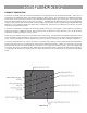
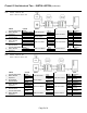
Each Preset 10 Architectural Two has six jumpers, JP1 through JP6, that select different modes of operation. The factory
default is to have all jumpers installed.
JP1 W hen this jumper is installed on the MASTER faceplate recording of presets is enabled. W hen removed, the TIME
and RECORD buttons are disabled. The position of JP1 on a SLAVE faceplate has no affect.
JP2 When this jumper is installed the faceplate takes on the MASTER duty. The MASTER faceplate is responsible for
transmitting and receiving DMX, storing presets and communicating with SLAVE faceplates. W hen removed, the
faceplate takes on the SLAVE duty. A SLAVE faceplate communicates button presses and mimics the state of the
LEDs on the master faceplate.
JP3 When this jumper is removed the Preset 10 Architectural Two will hold its last look upon loss of DMX input.
JP4 When this jumper is installed it enables SINGLE STATION MODE. In this mode the faceplate will not send any
"alternate start code" packets. When this jumper is removed it enables MULTI STATION MODE. This allows the
alternate start code packets required for master/slave station operation. If your system contains only one Preset 10
Architectural Two , there is no need to remove the jumper.
JP5 W hen this jumper is removed the DMX input is merged with the output of the active preset. The merge is Highest
Takes Precedence (HTP), where the output for each DMX channel is the highest level on any input for that channel.
JP6 When this jumper is installed the preset buttons act like “radio buttons”. Selecting a different preset releases the
current active preset. W hen this jumper is removed the preset buttons act in a push on, push off manner. All the
presets pile on to each other in Highest Takes Precedence (HTP). The OFF preset is an exception. See the details
in the section on POPO operation.
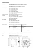
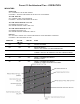
MASTER SELECTION
A typical system consists of a single MASTER faceplate. Shunt JP4 should be installed (default condition) for normal MASTER
operation. In a systems that contain slaves the shunt at JP4 should be removed. For safe keeping place the shunt over only
one of the pins at JP4.
SLAVE SELECTION
To modify a faceplate to become a SLAVE the shunts located at JP2 and JP4 should be removed. For safe keeping place the
shunt over only one of the pins at JP2 and JP4.