PRESET TEN ARCHITECTURAL TWO OWNERS MANUAL m odel PRE10-A2 Doug Fleenor Design 396 Corbett Canyon Road Arroyo Grande, CA 93420 (805) 481-9599 Software Version 1.
PRODUCT DESCRIPTION The Preset 10 Architectural Two is a further developm ent of our popular Preset 10 Architectural controller. The Preset 10 Architectural Two (PRE10A2) offers new features and different wiring options. The new features of the PRE10A2 include a grand m aster, pile on m ode (input + preset), jum per selectable button m odes (radio or push on/push off), and a two gang form factor that allows PRE10A2 to fit in all two gang back boxes.
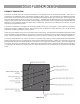
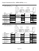
SPECIFICATIONS Connector: Phoenix Contact MSTB series 3 position two part term inal block Model: MSTB MSTB 2,5/3-ST-5,08 Order Num ber: 17 57 02 2 Phoenix Contact MSTB series 5 position two part term inal block Model: MSTB 2,5/5-ST-5,08 Order Num ber: 17 57 04 8 Connector pin out: 1 (C) 2 ( -) 3 (+) DMX512 com m on DMX512 data - (input) DMX512 data + (input) 1 2 3 4 5 DMX512 com m on DMX512 data - (output) DMX512 data + (output) Supply com m on (internally tied to pin1) Supply voltage “hot” (C) ( -)
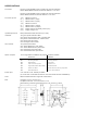
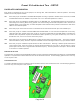
Preset 10 Architectural Two - INSTALLATION WIRING INFORMATION Preset 10 Architectural Two is designed to use daisy-chain wiring topology. Unlike its predecessor the Preset 10 Architectural, the Preset 10 Architectural Two has an input (TB2) and output (TB1) connector. Also note that a system m ay contain m ultiple power supplies when voltage drop becom es a concern. Please give us a call if you have any questions.
Preset 10 Architectural Two - INSTALLATION (continued) UP STREAM SLAVE Note: Master - Rem ove JP4 Slave - Rem ove JP2 & JP4 1 2 3 4 5 CABLE 120 Ohm Data Cable Belden 9829 or Equivalent (2) #16 AWG Stranded Wires 120 Ohm Data Cable Belden 9829 or Equivalent (2) #16 AWG Stranded Wires 120 Ohm Data Cable Belden 9829 or Equivalent COLOR Shield White/Blue Stripe Blue/White Stripe Black Red Shield White/Blue Stripe Blue/White Stripe Black Red Shield White/Blue Blue/White Stripe FROM TO 5 Pin XLR Plate Power
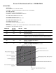
Preset 10 Architectural Two - SETUP FACEPLATE CONFIGURATION Each Preset 10 Architectural Two has six jum pers, JP1 through JP6, that select different m odes of operation. The factory default is to have all jum pers installed. JP1 W hen this jum per is installed on the MASTER faceplate recording of presets is enabled. W hen rem oved, the TIME and RECORD buttons are disabled. The position of JP1 on a SLAVE faceplate has no affect. JP2 W hen this jum per is installed the faceplate takes on the MASTER duty.
Preset 10 Architectural Two - OPERATION INDICATORS GREEN LED ON = CURRENTLY SELECTED PRESET FLASHING = TIME SETTING MODE SELECTED FOR THIS PRESET YELLOW TIM E LED ON = PRESET FADE IS IN PROGRESS FLASHING = TIME SETTING MODE SELECTED YELLOW GRAND M ASTER 100% LED ON=GRAND MASTER AT 100% OFF=GRAND MASTER LESS THAN 100% YELLOW GRAND M ASTER 0% LED ON=GRAND MASTER AT 0% OFF=GRAND MASTER GREATER THAN 0% RED LED ON = STATION LOCKED OUT / RECEIVING DMX512 FROM EXTERNAL CONSOLE FLASHING = RECORD MODE ACTIVE GREEN L
RECORDING PRESETS In order to set the individual dim m er levels recorded to a preset, the Preset 10 Architectural Two m ust be connected to a DMX512 source. W hen less than 512 dim m er levels are received, a level of 0% will be stored for all channels above those received. Note: ! ! For predictable results, avoid recording when the DMX levels are changing. Recording of presets m ust be done from the MASTER faceplate Using the prim ary DMX512 console, set a “look” to be recorded. 1.
PLAYBACK OF PRESETS Presets can be played back in one of two ways by “radio button” or “push on, push off” (POPO) m ode. Selection of the preset button m ode is m ade via JP6. In “radio button” m ode selecting a different preset releases the current active preset. The result is a crossfade from the current preset to the newly selected one. The tim e taken to fade from the current preset to the new preset is taken from the newly selected preset.