
User guide

Page 5 of 7
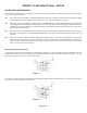
(Figure 2)
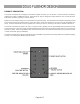
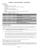
(Figure 1)
PRESET 10 ARCHITECTURAL - SETUP
FACEPLATE CONFIGURATION
Each Preset 10 Architectural has four jumpers, JP1 through JP4, that select different modes of operation. The factory default
is to have all jumpers installed.
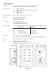
JP1 W hen this jumper is installed on the MASTER faceplate recording of presets is enabled. W hen removed, the TIME
and RECORD buttons are disabled. The position of JP1 on a SLAVE faceplate has no affect.
JP2 When this jumper is installed the faceplate takes on the MASTER duty. The MASTER faceplate is responsible for
transmitting and receiving DMX512, storing presets, and communicating with SLAVE faceplates. When removed, the
faceplate takes on the SLAVE duty. A SLAVE faceplate communicates button presses and mimics the state of the
LEDs on the master faceplate.
JP3 When the jumper is installed the Preset 10 operates as an architectural preset station. When this jumper is removed
the Preset 10 operates as a console backup/portable station. This jumper modifies the personality of the Preset 10
software.
JP4 When this jumper is installed it enables SINGLE STATION MODE. In this mode the faceplate will not send any
"alternate start code" packets. When this jumper is removed it enables MULTI STATION MODE. This allows the
alternate start code packets required for master/slave station operation. If your system contains only one Preset 10,
there is no need to remove the jumper.
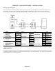
MASTER AND SLAVE SELECTION
In a system with more than one faceplate only one MASTER is allowed. To modify faceplate to become a MASTER which can
support SLAVE stations, the shunt located at JP2 should be installed and the shunt at JP4 should be removed. For safe
keeping place the shunt over only one of the pins at JP4.
To modify a faceplate to become a SLAVE the shunts located at JP2 and JP4 should be removed. For safe keeping place the
shunt over only one of the pins at JP2 and JP4.