GIZMO DMX512 TEST TOOL OWNERS MANUAL Doug Fleenor Design 396 Corbett Canyon Road Arroyo Grande, CA 93420 (805) 481-9599 Software Version 04/01/2006 Manual Revision 0 $ Serial # 05B075
Overview The Gizmo is a DMX512 test tool with features useful for lighting system setup, testing, troubleshooting, and commissioning. With the Gizmo you can transmit, receive, save, playback scenes and perform a variety of data and cable tests. It is housed in a rugged chassis made of 0.1" thick aluminum. A fitted carrying case and wall transformer/battery charger are included with each Gizmo. Direct channel access while sending or receiving DMX512 signals is possible through the use of the numeric keypad.
Using this manual When reading this manual the keypad of the Gizmo is represented with the following symbols. [TOP] [AND] [THRU] [AT] [CLEAR] [ENTER] [LIGHT] Top of menu AND THROUGH AT CLEAR / BACK MENU ENTER Toggle the backlight On / Off [>] [<] [Ç] [É] [Ü] [á] [Ö ] [Ñ ] Right / Next Left / Previous Up Down Full / 100% Zero / 0% Fast Forward Fast Rewind Menu Navigation TRANSMIT? ^¥ TO SCROLL The Gizmo always powers up to the top of the menu tree with “TRANSMIT?” as the first option.
Transmit TRANSMIT? ^¥ TO SCROLL The TRANSMIT mode is used to generate DMX512 data. By transmitting DMX512 you can assure that DMX512 receiving devices are operating correctly and diagnose problems. In order to transmit no incoming DMX512 can be present on the Gizmo’s DMX512 input. Press [ENTER] to select the TRANSMIT mode. There are four options within this menu. Use the [Ç] or [É] key to scroll between these options. Use the [ENTER] key to select the desired option.
Receive RECEIVE? ^¥ TO SCROLL The RECEIVE mode is used to monitor the levels of the incoming DMX512 data. While the Gizmo is in any of the receive modes, the levels are also re-transmitted out. The Gizmo is opto-isolated from input to output and the data is re-timed. These features allow the user to accurately diagnose the source of problems and to provide a known source of DMX512 data. Press [ENTER] to select the RECEIVE mode. There are five receive modes.
Receive (continued) Display Stats This menu option allows the user to examine some of the details of the DMX512 signal being received. Packet Length Displays the minimum, current, and maximum number of channels present in the DMX512 packets being received. Dashes will be displayed if no input signal is present. Note: The allowable number of channels is between 24 and 512. Break Length Displays the minimum, current, and maximum break length of the DMX512 packets being received.
Scene Mode SCENE MODE? ^¥ TO SCROLL The Gizmo can record 100 scenes. Each of the scenes contains a level for all 512 channels. Press [ENTER] to select the SCENE mode. There are two scene modes available. One is used to edit scenes and one is used to play back recorded scenes. Use the [Ç] or [É] key to scroll to the desired scene mode and the [ENTER] key to select that mode. Edit Scene This mode is used to build a complete scene and to record it as one of the 100 backup scenes.
Cable Test CABLE TEST? ^¥ TO SCROLL Press [ENTER] to select the CABLE TEST mode. The cable test allows the user to check 3 conductor or 5 conductor DMX512 cables. The cable under test is connected to the input and output connectors of the Gizmo. Pin 1 (shield) must be connected for the test to operate. If pin 1 is open, an error message indicates that condition. The two data pairs are tested independently.
Patch Mode PATCH MODE? ^¥ TO SCROLL In PATCH MODE the Gizmo takes the DMX512 input and reorganizes the channel numbers and transmits them creating a new “patch”. The Gizmo can store 10 user defined patches and has two predefined patches, a “1-1" and a “null” patch. Selecting the “1-1" patch sets output channels consecutively, so the input channels are equal to the output channels. Selecting the “null” patch clears all the output channels so no channels are output.
Setup SETUP? ^¥ TO SCROLL Press [ENTER] to select the SETUP mode. There are three options. Use the [Ç] and [É] keys to scroll through the selections and the [ENTER] key to select the displayed option. Software Version Entering the SETUP mode first displays the Gizmo software version which is shown as the release date for the installed software. New software is installed by replacing the socketed processor chip in the Gizmo. Check the Doug Fleenor Design, Inc. web site at www.dfd.com for the latest version.
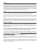
Specifications Input baud rate: Input circuit: Input signal: Input connector: 250 Kb/s ESD protected EIA-485 transceiver (LT1785) 3 volts minimum, 12 volts maximum Male Gold plated 5 pin XLR (Neutrik D-1 series). Pin 1 = common, Pin 2 = Data-, Pin 3 = Data+. Cable check on pin 4 and pin 5 Output isolation: 600 Volts Output baud rate: Output circuit: Output signal: Output connector: 250 Kb/s ESD protected EIA-485 transceiver (LT1785) DMX512-A Female Gold plated 5 pin XLR (Neutrik D-1 series).