
Operator`s manual


Table Of Contents
- Contents
- Figures
- Tables
- Safety
- Introduction
- Setting Up the 708-DS / 709-DS
- Operating the 708-DS / 709-DS
- Main Screen - Options
- Main Screen - Display Parameters
- Main Screen - Sample Temperatures
- Main Screen - Run
- Main Screen - Stop
- Main Screen - Drive Unit Up / Down
- Manual Drive Unit Up / Down
- Manual Sampling
- Main Screen - Manifold Up / Down
- Main Screen - Lock
- Main Screen - Unlock
- Main Screen - Remote Control
- Main Screen - Alarms
- Main Screen - Maintenance Due Icon
- Menu Screen - System Menu
- General 708-DS / 709-DS Conventions
- Agilent 708-DS / 709-DS Notifications
- Main Screen - Options
- Maintenance and Troubleshooting
- Index
Setting Up the 708-DS / 709-DS 3
708-DS / 709-DS Operator’s Manual 45
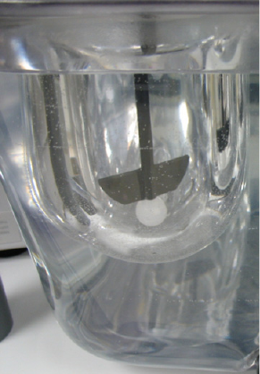
Figure 23 Inserting Height Spheres
3 Lower the drive unit to its operating position (until it stops).
4 With the shaft locking collars loosened, carefully lower each shaft
until the bottom of the paddle blade rests against the height sphere.
5 Ensure the shaft locking collar is flush against the top of the spindle
assembly by rotating each shaft until resistance is met.
6 Tighten each shaft locking collar securely.
7 Raise the drive unit to its home position.
8 Remove the height spheres from the vessels.