
Operator`s manual


Table Of Contents
- Contents
- Figures
- Tables
- Safety
- Introduction
- Setting Up the 708-DS / 709-DS
- Operating the 708-DS / 709-DS
- Main Screen - Options
- Main Screen - Display Parameters
- Main Screen - Sample Temperatures
- Main Screen - Run
- Main Screen - Stop
- Main Screen - Drive Unit Up / Down
- Manual Drive Unit Up / Down
- Manual Sampling
- Main Screen - Manifold Up / Down
- Main Screen - Lock
- Main Screen - Unlock
- Main Screen - Remote Control
- Main Screen - Alarms
- Main Screen - Maintenance Due Icon
- Menu Screen - System Menu
- General 708-DS / 709-DS Conventions
- Agilent 708-DS / 709-DS Notifications
- Main Screen - Options
- Maintenance and Troubleshooting
- Index
44 708-DS / 709-DS Operator’s Manual
3 Setting Up the 708-DS / 709-DS
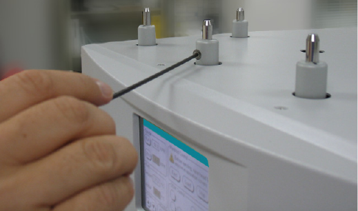
Figure 22 Tightening the Shaft Locking Collar
7 Raise the drive unit until sufficient clearance is available to move the
basket height gauge to the next position.
8 Repeat steps 2 - 7 for all remaining positions.
Setting Paddle (Apparatus 2) Heights
1 Ensure the drive unit is fully raised and the paddle shafts are pushed
up sufficiently.
2 Place a 25-mm height sphere in each vessel.