
Operator`s manual


Table Of Contents
- Contents
- Figures
- Tables
- Safety
- Introduction
- Setting Up the 708-DS / 709-DS
- Operating the 708-DS / 709-DS
- Main Screen - Options
- Main Screen - Display Parameters
- Main Screen - Sample Temperatures
- Main Screen - Run
- Main Screen - Stop
- Main Screen - Drive Unit Up / Down
- Manual Drive Unit Up / Down
- Manual Sampling
- Main Screen - Manifold Up / Down
- Main Screen - Lock
- Main Screen - Unlock
- Main Screen - Remote Control
- Main Screen - Alarms
- Main Screen - Maintenance Due Icon
- Menu Screen - System Menu
- General 708-DS / 709-DS Conventions
- Agilent 708-DS / 709-DS Notifications
- Main Screen - Options
- Maintenance and Troubleshooting
- Index
34 708-DS / 709-DS Operator’s Manual
3 Setting Up the 708-DS / 709-DS
Vessel Installation
1 Press Drive to move the drive unit to the fully raised position.
2 Carefully install the dissolution vessels in the vessel plate.
3 For the 708-DS vessel, engage the clips for each position over the
rim of the vessel to secure it in place.
For the 709-DS vessel, open the clip, install the vessel, and close the
clip.
4 If necessary, place the TruAlign blank vessel position covers on the
vessel plate openings at Position 7 and Position 8. Rotate the two
clips for each position over the cover to secure it in place.
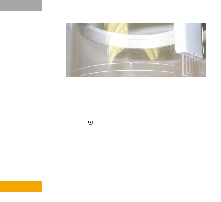
NOTE
Bubbles on the surface of the vessel, like the one centered in the figure
below, are not a manufacturing defect and will not affect performance.
Figure 11 Vessel Bubble
CAUTION
Ensure the connection pins in the vessel socket are aligned with the
holes on the vessel.