
Operator`s manual


Table Of Contents
- Contents
- Figures
- Tables
- Safety
- Introduction
- Setting Up the 708-DS / 709-DS
- Operating the 708-DS / 709-DS
- Main Screen - Options
- Main Screen - Display Parameters
- Main Screen - Sample Temperatures
- Main Screen - Run
- Main Screen - Stop
- Main Screen - Drive Unit Up / Down
- Manual Drive Unit Up / Down
- Manual Sampling
- Main Screen - Manifold Up / Down
- Main Screen - Lock
- Main Screen - Unlock
- Main Screen - Remote Control
- Main Screen - Alarms
- Main Screen - Maintenance Due Icon
- Menu Screen - System Menu
- General 708-DS / 709-DS Conventions
- Agilent 708-DS / 709-DS Notifications
- Main Screen - Options
- Maintenance and Troubleshooting
- Index
Setting Up the 708-DS / 709-DS 3
708-DS / 709-DS Operator’s Manual 29
Temperature Probe Installation (708-DS)
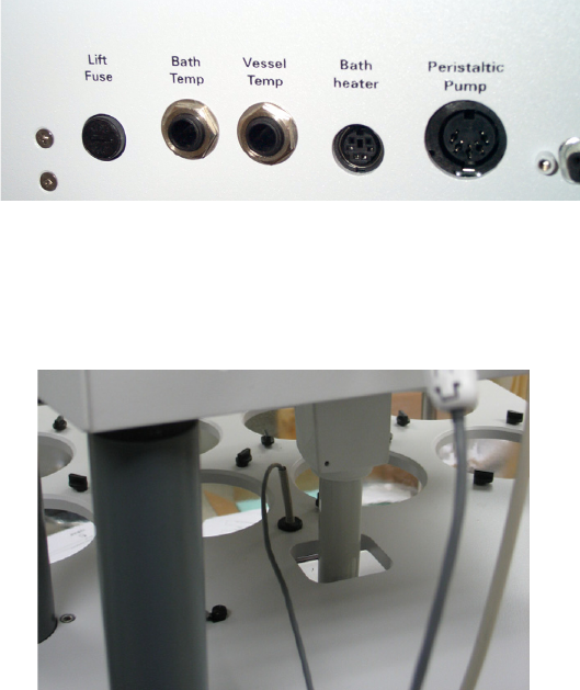
1 Insert the water bath temperature probe into the BATH TEMP jack
on the rear of the dissolution apparatus drive unit.
Figure 8 BATH TEMP Connector
2 Place the other end of the temperature probe through the hole in the
center of the vessel plate in the water bath.
Figure 9 Positioning the Temperature Probe