
Operator`s manual


Table Of Contents
- Contents
- Figures
- Tables
- Safety
- Introduction
- Setting Up the 708-DS / 709-DS
- Operating the 708-DS / 709-DS
- Main Screen - Options
- Main Screen - Display Parameters
- Main Screen - Sample Temperatures
- Main Screen - Run
- Main Screen - Stop
- Main Screen - Drive Unit Up / Down
- Manual Drive Unit Up / Down
- Manual Sampling
- Main Screen - Manifold Up / Down
- Main Screen - Lock
- Main Screen - Unlock
- Main Screen - Remote Control
- Main Screen - Alarms
- Main Screen - Maintenance Due Icon
- Menu Screen - System Menu
- General 708-DS / 709-DS Conventions
- Agilent 708-DS / 709-DS Notifications
- Main Screen - Options
- Maintenance and Troubleshooting
- Index
28 708-DS / 709-DS Operator’s Manual
3 Setting Up the 708-DS / 709-DS
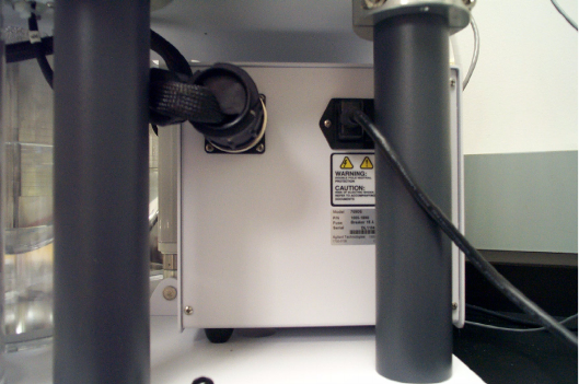
DVH Power Controller Setup (709-DS)
1 Install the DVH Power Controller box in the back of the 709-DS,
beneath the vessel plate. Ensure that the rubber feet of the control
box do not sit in any holes on the vessel plate.
2 Connect the cable attached to the vessel plate to the circular input on
the DVH Power Controller box.
3 Connect the communication cable (RJ-45) from the DVH Power
Controller box to the DVH Comm port on the back of the drive unit.
Figure 7 DVH Power Controller