
Operator`s manual


Table Of Contents
- Contents
- Figures
- Tables
- Safety
- Introduction
- Setting Up the 708-DS / 709-DS
- Operating the 708-DS / 709-DS
- Main Screen - Options
- Main Screen - Display Parameters
- Main Screen - Sample Temperatures
- Main Screen - Run
- Main Screen - Stop
- Main Screen - Drive Unit Up / Down
- Manual Drive Unit Up / Down
- Manual Sampling
- Main Screen - Manifold Up / Down
- Main Screen - Lock
- Main Screen - Unlock
- Main Screen - Remote Control
- Main Screen - Alarms
- Main Screen - Maintenance Due Icon
- Menu Screen - System Menu
- General 708-DS / 709-DS Conventions
- Agilent 708-DS / 709-DS Notifications
- Main Screen - Options
- Maintenance and Troubleshooting
- Index
Setting Up the 708-DS / 709-DS 3
708-DS / 709-DS Operator’s Manual 27
Figure 6 Raising the Stability Feet
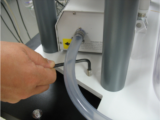
3 Using the 90º Allen key in the top of the front level-adjustment
screws, adjust the screws to achieve left-to-right level within
tolerance. It may be necessary to loosen the nut(s) beneath the base
plate to allow for adjustment.
4 Using the 90º Allen key in the top of the rear level-adjustment screw,
adjust the screw to achieve front-to-back level within tolerance. It
may be necessary to lift the heater / circulator to gain access to this
screw.
5 Verify the level of the dissolution apparatus with a bubble or digital
level.
6 Once the unit is leveled, use the open-end wrench to tighten the
nut(s) below the base plate.
7 Lower the side stability feet located toward the back on either side of
the base plate until they touch the laboratory bench. Do not
over-tighten to ensure level is maintained.
8 Reinstall the black caps on all of the screws.