
Operator`s manual


Table Of Contents
- Contents
- Figures
- Tables
- Safety
- Introduction
- Setting Up the 708-DS / 709-DS
- Operating the 708-DS / 709-DS
- Main Screen - Options
- Main Screen - Display Parameters
- Main Screen - Sample Temperatures
- Main Screen - Run
- Main Screen - Stop
- Main Screen - Drive Unit Up / Down
- Manual Drive Unit Up / Down
- Manual Sampling
- Main Screen - Manifold Up / Down
- Main Screen - Lock
- Main Screen - Unlock
- Main Screen - Remote Control
- Main Screen - Alarms
- Main Screen - Maintenance Due Icon
- Menu Screen - System Menu
- General 708-DS / 709-DS Conventions
- Agilent 708-DS / 709-DS Notifications
- Main Screen - Options
- Maintenance and Troubleshooting
- Index
24 708-DS / 709-DS Operator’s Manual
3 Setting Up the 708-DS / 709-DS
Tubing / Cable Connections
Complete the following sections to connect the necessary tubing and
cables for the Agilent 708-DS / 709-DS.
Heater / Circulator Setup (708-DS)
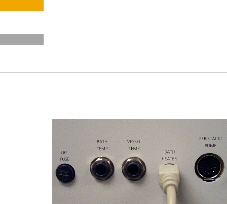
1 Connect the six-pin cable to the rear of the heater / circulator and the
other end into the position marked BATH HEATER on the
dissolution apparatus rear panel.
Figure 3 BATH HEATER Connector
CAUTION
Do not turn on the heater / circulator before filling the water bath to
avoid damaging the internal heating elements of the circulator.
NOTE
The Agilent Wide Input Range Heater / Circulator is pre-installed on the
apparatus at the factory. If reinstallation or replacement is required,
please refer to the Agilent Wide Input Range Heater / Circulator
Operator’s Manual (located on the Technical Documentation CD) for
complete installation instructions.