ICU300 / ICU300T Manual sliding doors with track guide system Installation Manual DL3107-020 – 05-2022 | EN |
ICU300 / ICU300T Manual Sliding Doors Track Installation Instructions Tools Required: Screwdrivers Small Straight (Flat Blade) - for Terminal Block wiring #2 Phillips (Crosspoint) - for various #8, #10, and #14 screws Wrenches / Sockets 15/16" wrench - for carrier and anti-rise roller adjustment Allen Wrenches 3mm - for “SX” & “SO” roller catch adjustment 1/8” - for “SO” arm stop & “SX” bottom pivot 5/32” - for “SO” top pivot 5mm (3/16”) - for “SO” arm pivot screw 7/32" - for “SX” breakout adjustment 5/16"
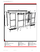
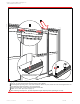
ICU300 / ICU300T Manual Sliding Doors Track Installation Instructions 2 4 3 3 8 4 1 10 7 7 5 12 11 11 8 12 5 9 6 6 9 8 1 Components (2 Leaf) - Overview 1 2 3 4 5 6 7 8 Header Header Closeout Cover Jamb Tube Cover Extrusion ICU300 / ICU300T DL3107-020 Sidelight Sliding Panel Positive Latch Pull Floor Rail 9 10 11 12 Floor Guide Bearing Pivot Top Bearing Pivot Bottom Latch Device 05-2022 3
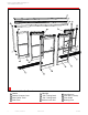
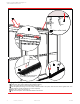
ICU300 / ICU300T Manual Sliding Doors Track Installation Instructions 3 2 1 4 4 12 12 6 6 8 8 12 5 9 11 12 10 9 5 11 7 11 7 10 11 2 Components (4 Leaf) - Overview 1 2 3 4 4 Header Header Closeout Cover Outer Roller Track Jamb Tube ICU300 / ICU300T 5 6 7 8 Sidelight “SX2” Sliding Panel “SX1” Sliding Panel Positive Latch Pull DL3107-020 9 10 11 12 Latch Device Floor Rail (2 Track) Floor Guide Bearing Pivot 05-2022
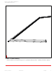
ICU300 / ICU300T Manual Sliding Doors Track Installation Instructions 3 Header to Jamb Assembly Fasten the header unit to the jambs using (4) #10 x 1” phillips pan heads (2 per side). (#2 Phillips screw driver required.
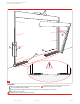
ICU300 / ICU300T Manual Sliding Doors Track Installation Instructions 2 1 2 2 3 4 4 Assembly 1 Place the header & jamb assembly into the rough opening. 2 Level all sides and shim as required. The mounting of the unit to the rough opening must meet applicable building codes and standards. 3 Fasten assembly into rough opening, after verifying unit is level and plumb in all directions. 4 Place floor track in position. Find highest floor elevation and shim accordingly.
ICU300 / ICU300T Manual Sliding Doors Track Installation Instructions approx. 80° 2 1 90° Adjustable Eccentric Bushing for alignment of “SO” panel against jamb in .03” increments 5 Sidelight mounting 1 - 2 Align “SO” panel 90° to the “SX” track and 80° to the vertical jamb. Place “SO” panel onto bottom pivot mounted on the jamb.
ICU300 / ICU300T Manual Sliding Doors Track Installation Instructions 2 4 1 55 3 5/16-18 x ½” 6 Securing the Sidelight 1 2 3 4 5 8 Push “SO” Panel vertically to align with jamb. Rotate upper “SO” arm and lightly fasten to screw plate located in header. Align and plumb “SO” Panel. Tighten (3) 1/4-20 x 5/8 fasteners in “SO” top pivot, securing “SO” Panel to header using 5/32” Allen wrench. Loosen fastener. Close “SO” panel and align “SO” magnet/latch sub-assembly.
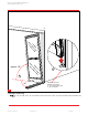
ICU300 / ICU300T Manual Sliding Doors Track Installation Instructions 1 4 1/4-20 Set Screw 3 2 Note: Pin should not touch bottom of track during slide operation. 7 Hanging the “SX” or “SX2” panel 1 Lift ”SX” or “SX2” panel and place rollers onto roller track in header. 2 Find the highest spot along track. Place small screwdriver below “SX” pivot, loosen set screw and re-tighten when “SX” bottom guide pin reaches screwdriver (1/8” Allen required). 3 Align track with jamb.
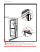
ICU300 / ICU300T Manual Sliding Doors Track Installation Instructions 2 4 1 Outer roller track 1/4-20 Set Screw 5 32 Note: Pin should not touch bottom of track during slide operation. 8 Hanging the “SX1” panel for telescopic 3 leaf and 6 leaf units 1 Install outer roller track by fastening into masonary opening. 2 Lift “SX1” panel and place rollers onto outer roller track. 3 Find the highest spot along track.
ICU300 / ICU300T Manual Sliding Doors Track Installation Instructions 3/16” 15/16” Wrench 5/16” Allen 1/64” AW AW CW CW 9 Vertical Alignment for “SX1” and “SX2” panels Using the eccentric carrier wheel (CW), and the anti-riser wheel (AW), level the sliding panel. Tighten hex nuts to secure the adjustment. Adjustment of the anti-riser roller: The anti-riser roller should not contact the top track anywhere along the slide path of the door.
ICU300 / ICU300T Manual Sliding Doors Track Installation Instructions 1 2 LOCK RAIL PIVOT RAIL LOCK RAIL PIVOT RAIL 3 B D C 4 A 10 9 Glazing 1 Remove the glass stops from exterior side (4 per opening). 2 Center the glass in opening. 3 Properly block and/or cushion glass edges. 4 Press the glass stops into place starting with the horizontal stops, then follow with the vertical stops.
ICU300 / ICU300T Manual Sliding Doors Track Installation Instructions 3 a b c d Note: It may be necessary to temporarily move deadstop bracket out of the way to access adjustment screw “d”. 1/8” Allen wrench required. 11 Adjustment of the Breakout-Unit 1. Loosen the set screws (a , b & c) to prevent interference while adjusting door. (7/32” Allen wrench required.) 2. Use the adjustment screw (d) to lift (CW) , or lower (CCW) , the leading edge of door. 3.
ICU300 / ICU300T Manual Sliding Doors Track Installation Instructions CCW raises the brass roller decreasing the tension. CW lowers the brass roller increasing tension. 12 Adjustment of the Roller Catch Align the roller catches, as illustrated, using the adjustment screws. (3mm Allen wrench tool required.) Pay close attention to the disengagement or breakout force. Do not exceed ANSI A156.10 Standards.
ICU300 / ICU300T Manual Sliding Doors Track Installation Instructions 90° 1/4-20 x ½” 90° 13 “SX1”, “SX2”, and “SO” Panel Breakout Adjustment 1. Open “SX” & “SO” panels to 90°. 2. Move arm stop blocks to engage arm. (1/8” Allen wrench required.) 3. Secure stop blocks.
ICU300 / ICU300T Manual Sliding Doors Track Installation Instructions 1/8” If Pin Needs To Be Adjusted Lower. Remove The Nut And Add Loctite 1 14 Positive Latch Adjustment 1. Remove astragral on side of door. 2. Adjust pin to provide 1/8” (3.2mm) of Latch Pin Engagement. 3. Test door for proper Latch operation and Breakout function. .
ICU300 / ICU300T Manual Sliding Doors Track Installation Instructions 15 Install Closeout Cover Attach Closeout Cover using 1/4” - 20 screws, one on either end. Ensure proper operation of door before installing Closeout Cover. If door is latched shut without proper Positive Latch adjustment, door will not open and Closeout Cover will be difficult to remove.
www.dormakaba.us dormakaba USA, Inc.