
User's Manual


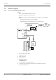


Table Of Contents
- Table of contents
- 1 About this Document
- 2 Grouped safety messages
- 3 Product Description
- 4 Design and function
- 5 Installation
- 5.1 Installation conditions
- 5.2 Installation diagram
- 5.3 Installation lines
- 5.4 Wall mounting
- 5.5 Cable routing
- 5.6 Setting the PoE switches
- 5.7 Connections
- 5.8 Vandal contact
- 5.9 Fastening the cover
- 6 Commissioning
- 7 Packaging/Return
- 8 Disposal
- Index

Installation Technical Manual
24 04045524 - 08/2016 Kaba access manager 92 32
5.2 Installation diagram
5.2.1 Access control with registration unit
Example:
• Access control with RFID registration units
• PoE power supply of the access manager
Method for feeding in the power supply via the PSE (Power Sourcing Equip-
ment):
– End span (direct supply, e.g. via PoE switch)
– Midspan (supply via intermediate sources, e.g. PoE injector)
1 Kaba access manager 92 32
2 Registration unit
3 Door opener key
4 Door opener
5 Door frame contact
Installation lines
A Coaxial cable to the registration unit
B Line to the door contact, the door opener key, and the door opener
C Ethernet network cable