
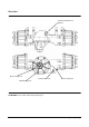
Specifications


Power Train Testing and Adjusting 51
5. Turn the ignition switch OFF and put the multimeter
on the 200 ohm range.
6. Check continuity between pins 4 and 7 of directional
switch connector with the switch in neutral.
Forward and then reverse the positions. There
should be continuity in neutral and no continuity in
forward and reverse.
a. If the above checks are correct, do Step 7.
b. If any of the above checks are not correct,
replace the directional control switch.
7. Check continuity between pins 1 and 2 of directional
switch connector in forward and then neutral
position. There should be continuity in forward and
no continuity in neutral. While the continuity is
checked in forward position, move the lever back
and forth (but stay in forward position) to see if the
resistance goes up or down. The resistance should
be constant.
a. If the above checks are correct, do step 8.
b. If the above checks are not correct, replace the
directional control switch.
8. Check continuity between pins 1 and 3 of directional
switch connector (1) in reverse and then neutral
positions. There should be continuity in reverse
and no continuity in neutral. While the continuity is
checked in reverse position, move the lever back
and forth (but stay in reverse position) to see if the
resistance goes up or down. The resistance should
be constant.
a. If the above checks are correct, do Step 9.
b. If any of the above checks are not correct,
replace the directional control switch.
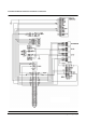
Transmission Control Harness Check
9. Disconnect the connector of Engine harness from
the connector of transmission harness. Check the
continuity of engine harness from one end to the
other. Repair or replace the wiring harness if there
is no continuity.
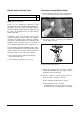
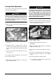
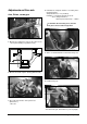
Transmission Solenoids Visual Check
10. A visual check can be done to see if the solenoid
plungers are moving.
Remove the modulating valve assemblies from the
transmission
11. Turn the ignition switch ON, DO NOT start the
engine. Release the parking brake.
12. Put the directional control switch in neutral.
Both solenoid plungers should be flush with the
solenoid.
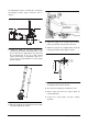
13. Put the directional control switch in forward and
then reverse.
The plunger of the solenoid that is activated should
move in approximately 3.18mm(.125 in).
14. If the solenoid plungers do not move as explained
in Steps 12 and 13, replace the defective solenoid.
15. If the solenoid plungers are good, the modulating
valves could be stuck or there is mechanical failure
in the transmission.