
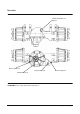
Specifications


Power Train Testing and Adjusting 50
Electric Control System Tests
Tools Needed
Digital Multimeter 1
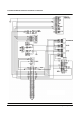
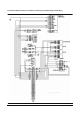
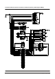
NOTE : Refer to Schematic.
Checks on the transmission directional control
electrical circuit can be done with a Digital Multimeter.
All voltage checks are made at the wiring harness
connectors with the ignition switch ON, DO NOT start
the engine. All continuity checks are done with the
ignition switch OFF.
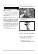
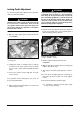
A beginning check of the direction control system
should be performed before testing the individual
components and wiring harness. When the direction
solenoids are energized they become magnetized. By
holding a metal screwdriver next to the solenoids it
can be determined whether they are energized or not.
Turn the ignition switch ON, DO NOT start the engine.
Release the parking brake. Place the direction control
switch in forward and check the forward solenoid for
magnetism. Do the same for the reverse direction.
z If the solenoids didn’t energize begin testing the
control system with step 1.
z If the solenoids did energize, go to step 10.
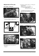
Directional Control Switch Check
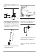
1. Put the directional control lever in neutral. Remove
the cover from the front side of front cockpit unit.
2. Disconnect harness connector from directional
control switch connector.
Directional Control Switch Connector
3. Engage the parking brake and turn the ignition
switch ON, DO NOT start the engine. Put the
multimeter on the 20 volt range.
4. Put the (-) probe on a good ground. Put the (+)
probe on socket 1 of harness connector.
a. If the indication is battery volts, do Step 5.
b. If the indications 0 volts, check the
Forward/Reverse fuse (No.3) located in the fuse
box and check the connecting wires for continuity.