
Specifications

Power Train Systems Operation 34
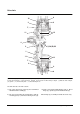
Selector spools
The selector spool circuits are arranged in such a way
that once a gear (forward or reverse) is selected the
opposite solenoid supply is shut off and drained. This
is done to prevent any electrical or malfunction of the
other solenoid from giving a sudden and unexpected
shift.
In addition the two selector spools are arranged so
they cannot select both forward and reverse at the
same time because they mechanically interfere with
each other.
The selector spools have two areas:
1. Slug area
2. Spool area
The slug cavity is exposed to system pressure all the
time. If the solenoid allows system oil to flow to the
end of the spool and pressurize the spool area then
the spool will move toward the slug because the spool
area is larger than the slug area and the force will be
higher. When the solenoid is closed, pressure to the
spool is reduced. This allows the pressure at the slug
to move the spool away from the slug.
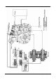
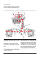
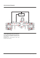
In fig.5 the selector spools are shown with forward
gear selected. Notice that the reverse solenoid supply
is drained through the forward spool.
Figure 5