
Specifications

Power Train Systems Operation 22
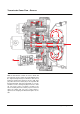
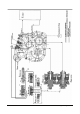
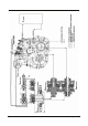
The basic components of the hydraulic system for
operating the transmission are transmission oil sump
(1), oil pump (2), primary oil filter (3), valve block,
containing main valve (4), orifice (5), inching valve (6),
modulating valve (7), selection valve (8), forward and
reverse solenoid valves (9,10), forward clutch (11),
reverse clutch (12), torque converter (14) with relief
valves (13,15), bypass (16) and oil cooler (17). The
pump is located in the torque converter housing, and
valve block is located on top of transmission, the filter
is located on the right hand of the transmission
housing.
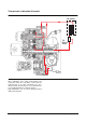
The transmission hydraulic system is explained in
three sections. The first section is the oil pump, filter,
torque converter and oil cooler systems. The second
section is the transmission lubrication system. The
third section is the transmission hydraulic control
system which controls the lift truck direction control.
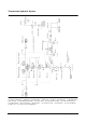
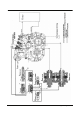
Pump, Filter, Torque Converter and
Oil Cooler Systems
The oil for the operation and lubrication of the
transmission is made available by pump (2). The
pump is located in the torque converter housing and is
driven by Tangs on the torque converter neck.
Oil sump (1), for the transmission, is in the bottom of
the transmission case. Oil from reservoir flows through
the strainer and internal channels to the suction side of
positive displacement pump .
Oil from pump (2) flows to primary oil filter (3). If there
is a restriction in the oil filter or if the oil is cold and
thick, a bypass valve in the filter will open. The
difference in pressure at which the bypass valve will
open is 124 ± 7 kPa (18 ± 1 psi). From the primary oil
filter, the oil flows on to main relief valve (4). In the
spool of main relief valve there is a bypass (18). The
purpose of this bypass is to supply lubrication and
coolant oil to the torque converter at low speeds and
especially during hot oil conditions. Converter relief
valve (13) protects the torque converter from oil
pressure higher than 670 kPa (97 psi), such as during
cold oil start-ups. At this pressure, the oil is released
back to the reservoir. Converter inlet passage has
converter bypass orifice (16). The purpose of this
orifice is to prevent too much of a pressure load on the
torque converter by allowing some of the oil to bypass
the converter. In converter outlet passage, there is
cooler bypass valve (15). Cooler bypass valve (15) will
release oil back to the reservoir if the oil pressure
reaches 400 kPa (58 psi). This can happen if the oil
cooler has a restriction or if the oil is cold and thick.
4
6
7
8
9
10