
Specifications

Power Train Systems Operation 17
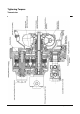
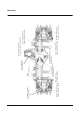
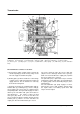
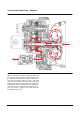
Transmission
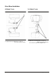
(1) TC Housing. (2) TM Bearing Plate. (3) TM Housing. (4) Torque Converter. (5) Input Shaft. (5A)Input Shaft Gear.
(6) Oil Pump. (7) Forward Gear. (8) Forward Clutch. (9) Reverse Shaft. (9A) Reverse Shaft Gear. (10) Reverse Clutch.
(11) Reverse gear. (12) Output gear. (13) U-joint. (14) Quill Shaft. (14A) Coupling. (15) PTO Pump. (16) Axle Lubrication
Pump.
The Transmission consists of 3 sections:
a) TC housing (1) which contains torque converter (4)
and the oil pump (6) and its housing. Tangs on the
TC neck engage in and drive the pump.
b) Bearing plate (2) which contains the rear bearings
of input, reverse shaft and output gear and the oil
supply channels. The oil channels are sealed by
the front TC housing wall.
c) Transmission housing (3) containing input shaft (5),
forward clutch (8), forward gear (7), reverse shaft (9),
reverse clutch (10), reverse gear (11), output gear (12)
and parking brake. The input shaft engages in and is
driven by the TC turbine hub spline and rotates in
same direction as the engine. It carries an input
shaft gear (5A) which is in mesh and drives the
reverse shaft gear (9A), the forward clutch (8) and the
forward gear (7), which is in mesh and drives the
output gear, when the forward clutch (8) is closed.
The reverse shaft (9) carries the reverse shaft gear
(9A), the reverse clutch (10) and the reverse gear (11)
which is in mesh and drives the output gear (12) when
the reverse clutch (10) is selected.
The quill shaft (14) is splined to the torque converter
and therefore rotates with engine speed and direction.
A coupling (14A) connects the PTO pump (15) to the
quill shaft (14).
The axle lubrication (16) pump engages in and is
driven by the reverse shaft. It always operates when
the engine rotates, but rotating speed varies with
torgue converter output.
9
16
15
14A
8
7
13
12
5
14
6
4
1
2
11
10
9A
5A
3