
Specifications

Power Train Systems Operation 16
Torque Converter
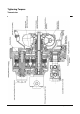
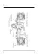
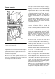
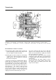
Torque converter
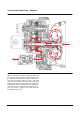
(1) Turbine. (2) Stator. (3) Impeller. (4) Housing.
(5) Stator support. (6) Stator clutch.
There is no direct mechanical connection between
engine and the transmission. Power from the engine is
transferred through the torque converter, which
hydraulically connects the engine to the transmission.
Transmission drive train oil is used to turn the turbine
and transmission input shaft.
When the lift truck works against a load, the torque
converter can multiply the torque from the engine and
send a higher torque to the transmission.
The torque converter has four main parts : housing (4),
impeller(pump) (3), turbine(1) and stator(2). The
housing is connected to the engine flywheel through a
flexplate. Impeller (3) and housing (4) are welded
together and turn with the engine flywheel at engine
speed and in the direction of engine rotation. Turbine
(1) turns the transmission input shaft. Stator (2) is
installed stationary on stator support (5) by a
freewheel clutch that allows one way rotation of the
stator.
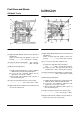
The hub, which is part of impeller (3), fits into the
transission oil pump. The turning impeller (3) rotates
the pump to supply oil for the operation of the torque
converter and transmission
When the engine is turning, oil flows through the
converter to lubricate and cool it. With the
transmission in neutral, the impeller, turbine, stator
and oil are all turning together in a direct fluid coupling.
The turbine/impeller speed ratio is 1/1.
Once a direction is selected the direct fluid coupling no
longer exists, the turbine/impeller speed ratio changes
(the turbine will be turning slower than the impeller).
When this happens the impeller outlet pressure to
turbine inlet pressure changes. This causes the oil
flow in the torus (fluid path containing the impeller,
turbine and stator) to gain momentum.
As impeller (3) turns, it increases the energy state of
the oil and directs the oil to the outside diameter of
converter housing (4). Oil leaving impeller (3) is
directed to turbine (1) where much of the oil? energy is
absorbed by turning the turbine. The pressure and
flow change in the torus becomes torque and speed at
the turbine and transmission input shaft.
Oil follows the turbine blades inward toward the center
of the converter. When the turbine/impeller speed ratio
is less than .85/1, oil is directed against the concave
side of stator (2) with enough force to stop its one way
rotation and lock the freewheel clutch.
Most of the energy from the oil that strikes the turbine
is used to turn the turbine, but some energy is left over.
Torque multiplication comes about because the locked
stator (2) directs this left over oil back to impeller (3) in
the same direction as the impeller rotation. This
energy force of the oil increases the torque on the
turbine and transmission input shaft. During operation,
this cycle is repeated over and over.
Without the stator, oil leaving the turbine is travelling in
a direction that is against impeller rotation. Torque
multiplication is only possible because of the stator.
4
2
6
5
1
3