
Service manual


Table Of Contents
G420F(FE) Service Manual Chapter 3. Engine Mechanical System
108
Connecting rods
1. When reinstalling, make sure that cylinder
numbers put on the connecting rod and cap at
disassembly match. When a new connecting rod i
s installed, make sure that the notches for holding
the bearing in place are on the same side.
2. Replace the connecting rod if it is damaged on
the thrust faces at either end. Also if step wear or
a severely rough surface of the inside diameter of
the small end is apparent, the rod must be
replaced aswell.
3. Using a connecting rod aligning tool, check the
rod for bend and twist. If the measured value is
close to the repair limit, correct the rod by a press.
Any connecting rod that has been severely bent or
distorted should be replaced.
Allowable bend of connecting rod : 0.05mm / 100
mm (0.0020in./3.94in.) or less
Allowable twist of connecting rod : 0.1mm / 100mm
(0.0039in./3.94in.) or less
Crankshaft bore mark location
Letters have been stamped on the end of the block
as a mark for the size of each of the 5 main journal
bores.
Use them, and the numbers or bar stamped on the
crank (marks for main journal size), to choose the
correct bearings.
Discrimination of cylinder block
CLASS MARK INSIDE DIAMETER
a A
59.000~59.006mm
(2.3228~2.3230in.)
b B
59.006~59.012mm
(2.3230~2.3233in.)
c C
59.012~59.018mm
(2.3233~2.3235in.)
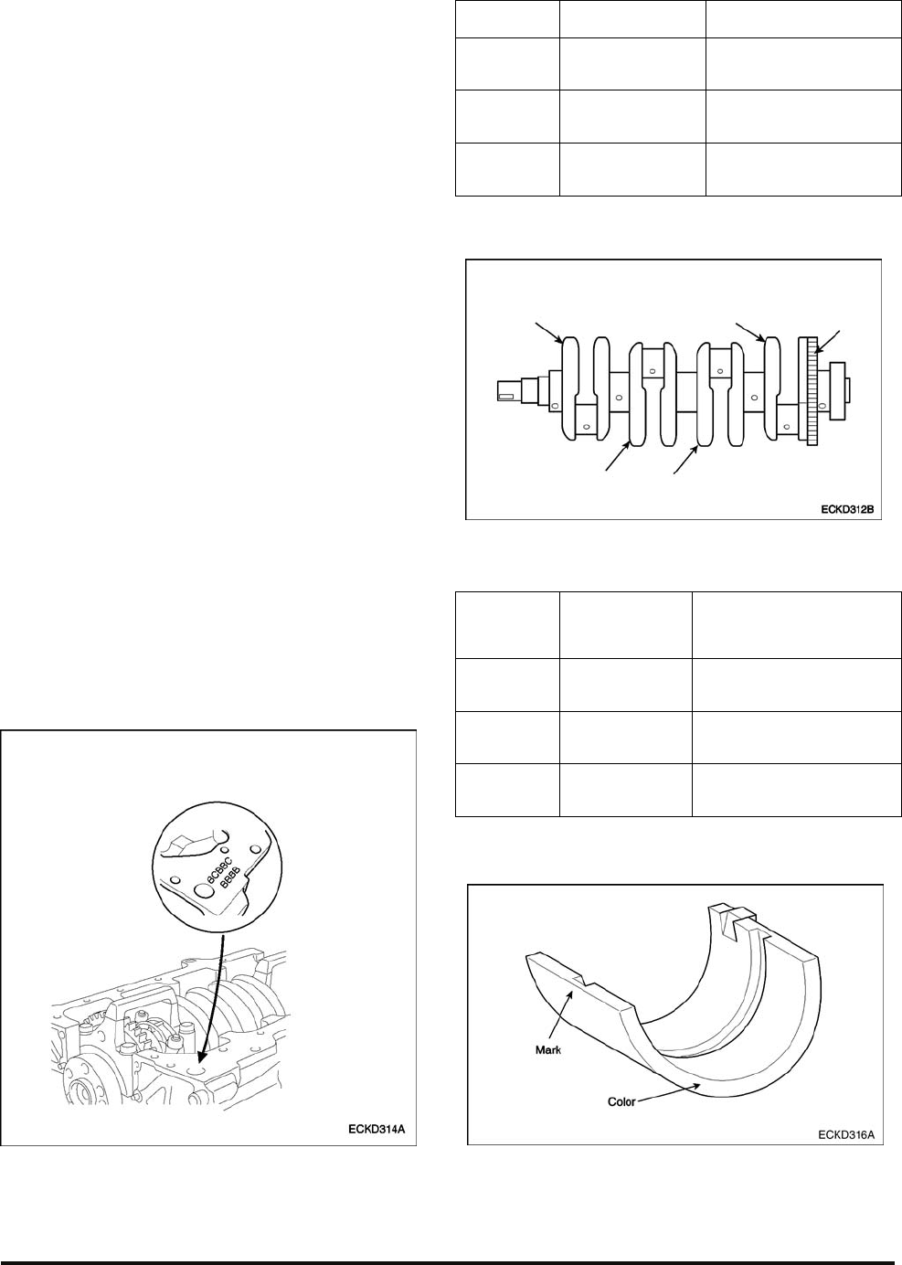
Crankshaft journal mark location
Discrimination of crankshaft
CLASS MARK
OUTSIDE
DIAMETER OF
JOURNAL
Ⅰ YELLOW
54.956~54.962mm
(2.1636~2.1638in.)
Ⅱ NONE
54.950~54.956mm
(2.1633~2.1636in.)
Ⅲ WHITE
54.944~54.950mm
(2.1631~2.1633in.)
Place of identification mark (Crankshaft bearing)