
User Manual


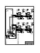

2.3.5 Controller and Two (2) 1 838-120 or 1838-121 Remote Call Stations
C.O.
PHN
Elevator
Control
RS 232
Connection
Main Terminal
4
1838 CONTROLLER
1
2
3
4
5
6
1
2
3
123 1716151413 2019
9
5
2
46 18
1
3
DOORKING, INC., INGLEWOOD, CA 90301
Date: Dwg. No. Rev.
Title:
7/12
A
RELAY 1 NORMALLY OPEN
RELAY 1 NORMALLY CLOSED
RELAY 1 COMMON
7
8
11
16 VAC
PWR
INPUT
16 VAC
PWR
INPUT
57 1211
Auxiliary Terminals
14
13
12
11
10
9
8
7
6
5
4
3
2
1
1838-120/121
- 12 VDC BATT INPUT
+12 V DC BATT IN PUT
+ 12 VDC
COMMON
DATA 1
DATA 0
NEG 12 VDC INPUT
POS 12 VDC INPUT
16 VAC OUTPUT
16 VAC OUTPUT
3
4
10
RED
WHT
BLK
GRN
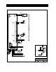
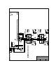
1838 Remote Call Stations - Telephone Interface
Wire Diagram
M1838-065-7
13
Relay 0
NO
NC
COM
RELAY 0 COMM O N
RELAY 0 NORMALLY CLOSED
RELAY 0 NORMALLY OPEN
9 10
1
Central Office phone line - touch tone, loop start.
A switch closure across terminals 4 & 6 will activate relay 1 for its
programmed strike time.
2
Battery Backup - separate batteries required for phone system and
weigand terminals.
3
16 Volt, 20 VA UL Listed Transformer.
4
4 conductor, stranded with overall shield, 18, 20, 22 or 24 gauge is
sufficient for these connections .
5
Aux power transformer must be connected. Otherwise, RS232, elevator
control and weigand inputs will not function.
6
16 VAC output can be used to power lights on card readers that have
additional lighting for outdoor use.
7
Weigand card reader or keypad connected to these terminals will operate
Relay 1 for its programmed strike time.
8
Electric strikes are wired to Normally Open (N.O.) contacts; magnetic
locks are wired to the Normally Closed (N.C.) contacts.
9
Power for electric strikes or magnetic locks is not provided by the system.
Use a separate UL listed power supply.
10
Use 18 AWG wire for runs up to 100 Ft. Use 16 AWG wire for runs up to
200 Ft.
11
12
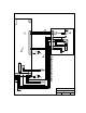
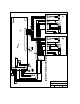
1838-120 uses a keypad. 1838-121 uses a card reader. The wiring is the
same regardless which device is used.
13
100 Feet maximum between remote call station and controller .
RED
WHT
BLK
GRN
12
Card Reader
Push To Call
GRN
14
13
12
11
10
9
8
6
7
5
4
3
2
1
LED Lights
GRY
ORG
Microphone
RED
GRN
WHT
WHT
WHT
PUR
Speaker
RED
WHT
BLK
GRN
12
Card Reader
Push To Call
GRN
14
13
12
11
10
9
8
6
7
5
4
3
2
1
LED Lights
GRY
ORG
Microphone
RED
GRN
WHT
WHT
WHT
PUR
Speaker
1838-120/121
RED
WHT
BLK
GRN
+ 12 VDC
COMMON
DATA 1
DATA 0
6
COM
MIC
BAT
WHT
RED
GRN
WHT
RED
GRN
WHT
RED
GRN
1494-010
5
14
1494-010 Microphone combiner required when using two call stations.
14
Page 20 1838-065-U-4-13