
User Manual


3.3 Switch Settings & Description
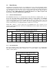
SW 1 (TOP SWITCH)
SWITCH FUNCTION SETTING DESCRIPTION
1 – 2 - 3 Elevator Shaft
Identification
Identifies which elevator shaft the MASTER board is controlling. See table 3, page
16 for switch matrix. Refer to section 3.2.1 for detailed information.
4 thru 7 Spare OFF Spare switches. Leave in OFF position
8 Relay
Activation
OFF Floor control relays WILL NOT energize when power is applied to the board.
ON Floor control relays WILL energize when power is applied to the board.
Switches 1-2-3: These switches identify which elevator shaft the 2348 circuit board is controlling.
Refer to the switch matrix (table 3) on page 16 for switch settings to identify elevator shafts 1 – 8.
Switches 4–7: Spare switches. Leave in the OFF position.
Switch 8: This switch sets the floor control relays to either energize or not energize when power is
applied to the circuit board. This switch setting is used in conjunction with the N.O. (Normally Open)
and N.C. (Normally Closed) relay setting on the circuit board. Refer to section 3.2.3 for more
information.
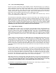
SW 2 (BOTTOM SWITCH)
SWITCH FUNCTION SETTING DESCRIPTION
1 – 2 Floor
Identification
Identifies which floors the elevator board is controlling. See table 4, page 16.
3 thru 7 Spare OFF Spare switches. Leave in OFF position
8 Lobby Hall
Call Relay
OFF
ON
Lobby Hall Call relay activates when visitor access is granted. Ground floor detect
input must be used if this switch is in the OFF position.
Lobby Hall Call relay not used.
Switches 1–2: These switches identify which floors the elevator board is controlling. Refer to the
switch matrix (table 4) on page 16 for switch settings to identify floors controlled.
Switches 3-7: Spare switches. Leave in the OFF position.
Switch 8: This switch should be in the OFF position if the Lobby Hall Up Call relay is used to call the
elevator car to the lobby (or ground) level when visitor access is granted. The ground floor detect
input must be used when this switch is in the OFF position. Floor control relay activation timing
starts when the ground floor detect input is activated. If the Lobby Hall Up Call relay is not used, this
switch must be in the ON position. Floor control relay activation timing starts when visitor access is
granted. Refer to section 3.2.4 for more information.
Page 18 2348-065-E-10-11