Owner’s Manual 1816 Telephone Intercom System DoorKing, Inc. 120 Glasgow Avenue Inglewood, California 90301 U.S.A. Phone: 310-645-0023 Fax: 310-641-1586 www.doorking.com P/N 1816-065 REV K, 12/11 Copyright 2005 DoorKing, Inc. All rights reserved.
Page 2 1816-065-K-12-11
Use this manual with the following models only. Model 1816 Telephone Intercom Systems with circuit board 1885-010, Rev A or higher. DoorKing, Inc. reserves the right to make changes in the products described in this manual without notice and without obligation of DoorKing, Inc. to notify any persons of any such revisions or changes. Additionally, DoorKing, Inc. makes no representations or warranties with respect to this manual. This manual is copyrighted, all rights reserved.
Table of Contents Preface Important Notices......................................................................................................................................................6 General Information ..................................................................................................................................................7 Features ............................................................................................................................................
3.5 3.6 3.7 Do Not Disturb Feature / Commands 3.5.1 Do Not Disturb Feature On / Off System Wide ........................................................................34 3.5.2 Set 1-Time Do Not Disturb Timer for Residents.......................................................................34 3.5.3 Schedule Do Not Disturb On / Off ............................................................................................35 3.5.4 Setting Do Not Disturb Schedule ..................................
FCC - UNITED STATES This equipment has been tested and found to comply with the limits for a class A digital device, pursuant to Part 15 of the FCC Rules and Regulations. These limits are designed to provide reasonable protection against harmful interference when the equipment is operated in a commercial environment.
General Information Prior to beginning the installation of the telephone entry system, we suggest that you become familiar with the instructions, illustrations, and wiring guidelines in this manual. This will help insure that you installation is performed in an efficient and professional manner. The proper installation of the telephone entry panel is an extremely important and integral part of the overall access control system.
Page 8 1816-065-K-12-11
Section 1 - Installation 1.1 General Information The DoorKing Model 1816 telephone intercom system provides communication to, and control of, a door (or gate) for up to 1200 users without the need for a dedicated Central Office (C.O.) phone line. This eliminates monthly line charges and equipment lease payments to the telephone company.
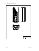
35.0 35.25 Main and Auxiliary Cabinets 33.0 1.1.1 11.25 .875 KO 2-places 5.125 3.0 13.25 2.25 1.0 R 2.5 5.125 7.875 10.5 13.0 DOORKING, INC., INGLEWOOD, CA 90301 Title: Date: Page 10 Main Cabinet / Auxiliary Cabinet - Large P/N 1816-080 / 1816-081 1/05 Dwg. No. M1816-065-1 Rev.
Garden Style Cabinet 21.0 21.25 19.0 1.1.2 11.25 .875 KO 2-places 5.125 3.0 13.25 2.25 1.0 R 2.5 5.125 7.875 10.5 13.0 DOORKING, INC., INGLEWOOD, CA 90301 Title: Date: 1816-065-K-12-11 Garden Style Cabinet P/N 1816-082, 1820-082, 1820-083 9/04 Dwg. No. M1820-065-2 Rev.
1.2 RJ71C Phone Block Installation The RJ71C wiring configuration is not recognized by all telephone companies. For Bell Canada, which has jurisdiction for Ontario and Quebec, refer to CA-79X jack for interconnect to the 1816 system. For BC Tel, which has jurisdiction in British Columbia, refer to BC Tel CRTC Spec 182 B5. 1. 2. 3. 4. 5. 6. 7. Place the order for the RJ71C phone block installation with the local telephone company at least three weeks in advance of the 1816 system installation.
A Line 1 TIP - Pin 1 Line 1 RING - Pin 2 Line 2 TIP - Pin 3 Line 2 RING - Pin 4 Line 3 TIP - Pin 5 Line 3 RING - Pin 6 Incoming Central Office Phone Lines - 12 Max Line 4 TIP - Pin 7 Line 4 RING - Pin 8 Line 5 TIP - Pin 9 Line 5 RING - Pin 10 Line 6 TIP - Pin 11 Line 6 RING - Pin 12 Line 7 TIP - Pin 13 Line 7 RING - Pin 14 Line 8 TIP - Pin 15 Line 8 RING - Pin 16 Line 9 TIP - Pin 17 Line 9 RING - Pin 18 Line 10 TIP - Pin 19 Line 10 RING - Pin 20 Line 11 TIP - Pin 21 Line 11 RING - Pin 22 Line 12 TIP - Pin
1.3 Cabinet, Relay and Component Identification For identification purposes, the Main Control Cabinet is defined as that part of the 1816 system that houses the main processor control board, and at least one, but not more than five, relay boards. Auxiliary Cabinets are defined as that part of the 1816 system that houses one decoder board, and at least one, but not more than eight, relay boards. Each cabinet is identified with a label and the system relays that it houses.
Auxiliary Cabinet 2 Auxiliary Cabinet 1 Board Auxiliary Cabinet 0 Board Main Cabinet Board Board 29 21 13 5 Board Board Board Board 28 20 12 4 Board Board Board Board 27 19 11 3 Board Board Board Board 26 18 10 2 Board Board Board Board 1 25 17 9 Board Board Board 24 16 8 Board Board Board 23 15 7 Board Board Board 22 14 6 Decoder Board Decoder Board Decoder Board Selector Switches Selector Switches Cabinet Labels Auxiliary Cabinet 2 Auxili
1.3.3 Relay Boards Each Relay Board has 12 relays on it numbered 00 through 11. One relay board is required for every 12 phone lines that the system interfaces with. These relays are identified to the main processor as a four digit relay number beginning with 0000 and increasing sequentially up to the maximum of 1199. Each cabinet has a label which identifies the cabinet number and the system relay numbers. Relay boards in the main cabinet are numbered 1 – 5.
Decoder Board Selection Switch Matrix Auxiliary Cabinet 1 2 3 4 5 6 7 8 0 ON ON ON ON ON ON ON ON 1 ON ON ON ON ON ON ON OFF 2 ON ON ON ON ON ON OFF ON 3 ON ON ON ON ON ON OFF OFF 4 ON ON ON ON ON OFF ON ON 5 ON ON ON ON ON OFF ON OFF 6 ON ON ON ON ON OFF OFF ON 7 ON ON ON ON ON OFF OFF OFF 8 ON ON ON ON OFF ON ON ON 9 ON ON ON ON OFF ON ON OFF 10 ON ON ON ON OFF ON OFF ON 11 ON ON ON ON OFF ON
Page 18 1816-065-K-12-11
Section 2 - Wiring Prior to installing wiring to the telephone entry system, we suggest that you become familiar with the instructions, illustrations, and wiring guidelines in this manual. This will help insure that you installation is performed in an efficient and professional manner. This telephone entry system contains a number of static sensitive components that can be damaged or destroyed by static discharges during installation or use.
2.1 Wiring Detail – Garden Style Cabinet 1816 Telephone Intercom System Wiring Detail - Garden Style Control Cabinet INCOMING C.O. PHN LINES Resident Telephone 9 10 8 7 11 Lobby Panel 11 12 13 14 15 16 17 18 19 20 21 22 23 24 2 6 4 Doorman Telephone C.O. PHN 16 VAC PWR INPUT 3 1 1 2 3 4 5 6 1 16 Volt, 40 VA UL Listed Transformer. 2 Earth Ground. 3 Optional Central Office phone line - touch tone, loop start. 4 Doorman Telephone (Optional). 5 Lobby panel.
2.2 Wiring Detail – Large Main Cabinet 1816 Telephone Intercom System Wiring Detail - Large Control Cabinet INCOMING C.O. PHN LINES Resident Telephone 9 10 8 11 1 2 3 4 5 6 7 8 9 10 1 2 3 4 5 6 7 8 9 10 8 RJ71C phone block. See drawing M1816-065-6 for detail. 9 Incoming phone lines from Central Office. 10 Outgoing phone lines to individual apartments. 11 DoorKing connecting cable. 11 12 13 14 15 16 17 18 19 20 21 22 23 24 7 2 Lobby Panel C.O.
2.
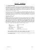
2.4 Main Circuit Board Terminal Description Terminal Description 1 2 3 4 5 6 Decoder Board Connection. Decoder boards are required with 1816 systems that use more than 5 relay boards. 7 8 9 10 11 Postal Switch – A switch closure across terminals 11 and 24 will cause the relay on the 1885 board to activate for its programmed strike time.
2.5 Entry System / Central Office Gain Adjustment This section applies to 1885-010 REV S boards and higher. These potentiometers are adjusted when more than one entry panel is attached to the 1816 system. By default, both are set to the fully counter-clockwise (minimum gain) position and both should be left in this position when a single entry panel is attached to the system. ES OUT is used to adjust signal gain to the entry system lobby panel.
Section 3 – Programming 3.1 System Set Up The system has default settings for most programming functions. When installing a new system, there is some set up programming required which will format the system to meet the operational requirements of the installation. Once the system is set up, there are also operational programming steps for the Doorman/Concierge phone and for tenant phones.
3.1.3 Last Available Relay The 1816 is capable of working with up to 1200 telephones, i.e. it can select one of up to 1200 system relays that are numbered 0000 through 1199. You must program into the system the last relay number that is available. Determine how many relay boards are connected to the system, then using the chart below, select the last available relay. For example, if your system uses 55 relay boards, the last relay available is 0671. Factory Default = 0011 1. 2. 3. 4.
3.1.4 Setting the System Time Clock This programming sequence sets the internal time clock in the 1816 system. (Note – if you only want to set the time, you can stop after step 4). Factory Default = (Not Programmed) 1. 2. 3. 4. 5. 6. 7. 3.1.5 Take the doorman telephone off hook. Press *33 and enter the four-digit MASTER CODE _ _ _ _ (beep). Enter the hour and minutes (HHMM) _ _ _ _ then press * (beep). Enter 0 for AM; or enter 1 for PM _ then press * (beep).
3.1.7 Number of Rings / Ring Type This programming sequence sets up the 1816 system for: 1) the number of rings allowed before the system automatically hangs up, 2) a single or double ring. A two digit number will be entered to set up these operating parameters, with each number of the code corresponding to the respective functions listed. Factory Default = 31 1. Take the doorman telephone off hook. 2. Press *04 and enter the four-digit MASTER CODE _ _ _ _ (beep). 3.
3.2 Directory Codes The four digit directory code is the number that is entered on the doorman/concierge or on the lobby telephone keypad to communicate with a particular tenant in the building. The directory codes start at 0000 and increase sequentially up to the maximum number of relays being used in the system. For example, if 100 residents are connected to the 1816 system, the directory codes being used will be 0000 for the first resident, up to 0099 for the 100th resident.
3.2.2 Turning Programmable Directory Codes On / Off The programmable directory codes can be turned "ON" or "OFF" after they have been programmed. It will be necessary to turn this feature off if any trouble shooting of the system is ever required. Turning the programmable directory code feature off does not cause the system to erase any directory codes that have been previously programmed. Factory Default = 1 (Off) 1. Take the doorman telephone off hook. 2.
3.3 Dedicated Phone Line Access An optional dedicated central office (C.O.) phone can be connected to the 1816 system. Connecting a C.O. line to the system provides additional functions available to the doorman/concierge and the lobby panel can be programmed to dial an outside line under certain circumstances. It also allows remote programming via a PC and modem when using a DoorKing 1833, 1834, 1835 or 1837 as the lobby panel. 3.3.
3.3.3 Erase Preprogrammed Phone Number This sequence allows you to erase individual preprogrammed phone numbers. Factory Default = (Not Programmed) 1. Take the doorman telephone off hook. 2. Press *11 and enter the four-digit MASTER CODE _ _ _ _ (beep). 3. Enter the four-digit directory code of the number to be erased (4000-9999) _ _ _ _ then press * (beep). 4. Repeat steps 3 to erase additional numbers. 5. Hang up the doorman telephone to end the programming session. 3.3.
3.4 Entry Codes Entry codes are a four digit number (preceded by #) than can be entered on the Doorman telephone keypad to gain access through the door or gate. When a programmed entry code is entered on the Doorman telephone keypad, the relay on the 1816 control panel will activate for the programmed strike time. The maximum number of entry codes that can be stored in the 1816 memory is 10,000. Use the log sheet provided in the back of this manual to record your entries. 3.4.
3.5 Do Not Disturb Features / Commands The Do Not Disturb feature provides time zones that prevents calls from the lobby panel to ring up to a resident. 3.5.1 Do Not Disturb Feature On / Off – System Wide This determines if the system will allow the do not disturb features to be active, or prohibits the do not disturb features from functioning.
3.5.3 Scheduled Do Not Disturb On / Off This programming sequence is used by the doorman or system administrator to turn the preprogrammed do not disturb schedule on or off. Note: If programmable directory codes are used, enter the directory code number instead of the relay number in step 3. Factory Default = 0 (Off) 1. Take the doorman telephone off hook. 2. Press *22 and enter the four-digit MASTER CODE _ _ _ _ (beep). 3.
3.6 Call Forwarding Features / Commands The Call Forwarding feature provides options that can forward lobby panel calls for a resident to a forwarding number. There are several options available on how a call is forwarded and system administrators should review all these options. 3.6.1 Set Up for Call Forwarding - System Wide This determines how the call forwarding feature will function system wide. Four options are available: 0. Call forwarding is turned off. 1.
3.6.3 Program Call Forward Numbers This programming sequence is used by the doorman or system administrator to program call forward numbers for residents. If option 3 was selected in 3.6.1, then the area code will be checked to see if it is allowable or not. If not allowed, the system will ring the resident’s phone. Note: If programmable directory codes are used, enter the directory code number instead of the relay number in step 3. Factory Default = (Not Programmed) 1.
3.6.5 Program Call Forward Allowed Area Codes This programming sequence is used by the doorman or system administrator to limit which area codes can be called when option 2 is selected in 3.6.1. This is a feature to prevent toll charges being incurred on calls forwarded through the phone line connected directly to the 1816 control panel. If a call forwarding area code does not match an area code programmed here, then the call is routed to the resident’s phone.
3.7 Virtual Doorman The virtual doorman is an independent system that provides communication from the lobby area to a company that provides doorman services. The virtual doorman service is completely separate from the 1816 system and does not utilize the 1816 lobby panel or any communication circuits provided by the 1816 system.
Page 40 1816-065-K-12-11
SECTION 4 – OPERATING INSTRUCTIONS 4.1 Administrator and Doorman Commands These commands are used by the System Administrator, Doorman, Concierge or Security Desk to access various features of the 1816 system. 4.1.1 Lobby Panel On / Off This programming sequence is used by the doorman or system administrator to turn the lobby panel On or Off. Factory Default = 1 (On) 1. Take the doorman telephone off hook. 2. Press *12 and enter the four-digit MASTER CODE _ _ _ _ (beep). 3.
4.1.5 Calling the Doorman or Lobby Panel from an Off Site Location A dedicated C.O. phone line must be connected to the 1816 control panel for this feature to be operable. This feature allows managers to place a call to the Doorman or lobby panel from an off site location. To call the doorman phone: 1. Call the phone number of the C.O. line attached to the 1816 system. The 1816 will answer with a short tone (beep). 2. Press #1 to be connected to the doorman phone. 3.
4.2 Technician Commands The following commands should be used by trained technicians only and are designed for trouble shooting purposes. 4.2.1 Reset Main Control Board This programming sequence will reset the 1885 main control board to the factory default values. This function will take about 5 minutes to complete. 1. 2. 3. 4. Take the doorman telephone off hook. Press *91 and enter the four-digit MASTER CODE _ _ _ _ (beep). Enter 9 9 9 9 then press * (beep).
4.2.2 Reset Main Control Board Resident Programming This programming sequence will reset the programming specific to each resident to the 1885 main control board to the factory default values. This function will take about 5 seconds to complete. The power LED on the main control board will flash during the process. NOTE: This command will perform command function 91 (4.2.1) automatically. 1. 2. 3. 4. Take the doorman telephone off hook. Press *90 and enter the four-digit MASTER CODE _ _ _ _ (beep).
Appendix You can use these tables to help organize some of the programmed features of the 1816 system. Make copies of the table on the next page to help organize resident information. Make copies of the RJ71C Forms as they will be needed when installing these phone blocks. RJ71C forms are available in electronic format on our tech support web-site at www.dkaccess.com. You may also copy the Resident Instruction Sheet. Just fill in the blanks. Programming Section Description 3.2.
Name Page 46 Apt Phone # System Relay # (Dir Code) Programmed Dir Code DND Schedule Call Fwd # Entry Code 1816-065-K-12-11
RJ71C / Relay Board Identification Model 1816 Main Cabinet RJ71C Board # Phone Number 1 RJ71C Board # Phone Number 2 RJ71C Pins Input/Output Phone Number 3 4 Phone Number Relay Phone RJ71C Pins Apt Dir Code Number Number Input/Output Number 00 1,2 / 27,28 00 3,4 / 29,30 01 3,4 / 29,30 01 5,6 / 31,32 02 5,6 / 31,32 02 7,8 / 33,34 03 7,8 / 33,34 03 9,10 / 35,36 04 9,10 / 35,36 04 11,12 / 37,38 05 11,12 / 37,38 05 13,14 / 39,40 06 13,14 / 39,40 06 15,16 / 41,42 07 15,16
RJ71C / Relay Board Identification Model 1816 Auxiliary Cabinet RJ71C Board # Phone Number 1 RJ71C Board # Phone Number 2 RJ71C Board # Phone Number 3 RJ71C Board # Phone Number 4 Page 48 RJ71C Pins Input/Output Cabinet No.
Resident Instructions Your building has been equipped with a DoorKing Telephone Intercom System that will provide communication for your guest from the lobby door to your home by use of the telephones in your home. If you have any questions regarding the use or operation of this system, please see your system administrator (building manager / HOA representative).