
Manual


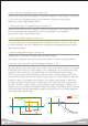
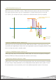
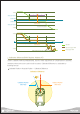

Maximum operational angle in Raw Data.
Maximum Position(RAM Register Address 22)
When requested position angle is greater than r(Max Position), "Exceed Allowed POT Limit" in
r(Max Position) becomes active and the operation is limited to r(Max Position).
Default value is 0x3EA(approximately 159.8˚). Refer to conversion chart in
(Pg 53)
for actual angle.
Shows the Proportional Gain. Increasing the Position Kp increases, the response time but over
response (vibration, overshoot) will result if the increase is too large.
Position Kp(RAM Register Address 24)
Shows the Derivative Gain. Increasing the Position Kd will suppress the over response (vibration,
overshoot) from Position Kp but unstability may result if the increase is too large.
Position Kd(RAM Register Address 26)
Shows the Intergral Gain. Applied to correct small offset in Steady State. May result in response
lag if the increase is too large.
Position Ki(RAM Register Address 28)
Shows Position Feedforward 1
st
Gain. Applied to increase Servo response time.
Position Feedforward Kd(RAM Register Address 30)
Shows Position Feedforward 2
nd
Gain. applied to increase Servo response time.
Position Feedforward Kdd(RAM Register Address 32)
Shows the Alarm LED blink period set by the LED Policy when error occurs. 1 is equivalent to 11.2ms.
Default value is 0x2D(Approximately 504ms).
LED Blink Period(RAM Register Address 38)
Temperature / Input voltage error check interval, 1 is equivalent to 11.2ms. Error activated if the
Temerature / Input voltage error lasts longer than the check interval.
Default value is 0x2D(Approximately 504ms).
ADC Fault Check Period(RAM Register Address 39)
Incomplete Packet error check interval, 1 is equivalent to 11.2ms. Incomplete Packet is deleted if it
remains longer than the check interval. Default value is 0x12(Approximately 201ms)
Packet Garbage Check Period(RAM Register Address 40)
35