
Manual


※ Whe Alarm LED is activated by the r(Status Error)or r(Alarm LED Policy), value in r(LED Control)
is ignored.
※ Turn / Velocity Control : Infinite Turn(Continuous Rotation) Mode.
Shows the ADC(Analog Digital Conversion) value of the input voltage in raw data. The conversion
formula to actual voltage is shown below. Refer to the voltage ADC conversion table in page 49.
Voltage = 0.074 X ADC
Voltage(RAM Register Address 54)
Shows the ADC(Analog Digital Conversion) value of the current temperature in raw data.
Refer to temperature ADC conversion table in page 51.
Temperature(RAM Register Address 55)
Shows actual length of the servo tick time. Tick time can be changed from 0 ~ 255, tick time reverts
back to 0 after 255. 1 is equivalent to 11.2ms, 255 is equivalent to 2.856sec.
Tick(RAM Register Address 57)
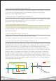
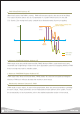
Shows Calibrated Position in raw data. The relationship between Calibrated Position and Absolute
Position is as follows.
Calibrated Position(RAM Register Address 58)
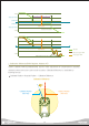
Shows the current control mode of the servo, I_JOG / S_JOG CMD Packet is used to change the mode.
Current Control Mode(RAM Register Address 56)
0x02 : Blue
0x04 : Red
Calibrated Position = Absolute Position - r(Calibration Difference, 47 Address)
Degree = Position Raw Data X 0.325
When r(Torque Control) is used to change the servo state to Torque On, servo first refers to
r(Current Control Mode). For example, dafault mode of the servo when it is first powered up is
“Position Control Mode” and when the servo state is changed to Torque On, mode remains at
“Position Control Mode”. Servo has to be at Off state to change the control mode to “Turn/Velocity
Control Mode”. With Torque Off, use I_JOG / S_JOG CMD to switch to “Turn/Velocity Control Mode”.
After the switch, use r(Torque Control ) to to turn Torque On and the mode will have switched to
“Turn/Velocity Control Mode”.
0 : Position Control
1 : Turn / Velocity Control
31