
Manual

ADC Fault
Detection Period
Packet Garbage
Detection Period
Stop Detection Period
Overload Detection Period
Stop Threshold
Inposition Margin
Reserved
Reserved
Calibration Difference
Status Error
Status Detail
Reserved
Reserved
Torque Control
LED Control
Voltage
Temperature
Current Control Mode
Tick
Calibrated Position
Absolute Position
Differential Position
PWM
Reserved
Absolute Goal Position
Absolute Desired
Trajectory Position
Desired Velocity
39
40
41
42
43
44
45
46
47
48
49
50
51
52
53
54
55
56
57
58
60
62
64
66
68
70
72
1
1
1
1
1
1
1
1
1
1
1
1
2
1
1
2
2
2
2
2
2
2
2
2
2
2
1
0x00 ~ 0xFE
0x00 ~ 0xFE
0x0000 ~ 0x7FFF
0x00 ~ 0xFE
0x00 ~ 0xFE
0x00 ~ 0xFE
-
-
-128 ~ 127
0x00 ~ 0x7F
0x00 ~ 0x7F
-
-
MASK : 0x60
0x00 ~ 0x07
0x00 ~ 0xFE
0x00 ~ 0xFE
0 ~ 1
0x00 ~ 0xFF
-
-
-
-
-
-
-
-
Temp/Voltage error check interval
11.2ms/Tick, 0x2D : 504ms
Packet Error check interval,
11.2ms/Tick, 0x12 : 201ms
Stop detection check interval,
11.2ms/Tick, 0x1B : 302ms
Overload check interval,
11.2ms/Tick, 0x96 : 1.68s
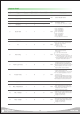
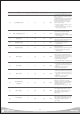
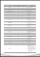
Type
ADDRESS
Bytes Valid Range Description
25
Reserved
Reserved
Reserved
Reserved
Reserved
Uncalibrated goal position Raw Data
Current intermediate goal position in trajectory
Desired speed based on speed profile Raw Data
Torque enable states (Refer to Pg 28)
0x01:Green, 0x02:Blue, 0x04:Red
Input voltage Raw Data, 8Bit
(Refer to detail in Pg 31)
Current temp Raw Data, 8Bit
(Refer to detail in Pg 31)
0 : Position Control,
1 : Turn / Velocity Control
11.2ms/Tick
Calbrated current position Raw Data 10Bit(0~1023)
Uncalibrated absolute position Raw Data
Position change/11.2ms
Torque Raw Data
Stop Threshold
Offset Threshold
Servo compersation
Refer to Pg 39
Refer to Pg 39
RW
RW
RW
RW
RW
RW
RW
-
-
RW
RW
RW
-
-
RW
RW
RO
RO
RO
RO
RO
RO
RO
RO
-
RO
RO
RO