
Manual
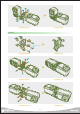
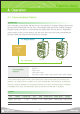
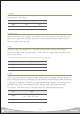

All the Servo to Servo connectors have same Pin assingment as the diagram below.
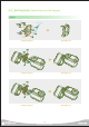
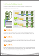
Multi Drop Network makes expansion easy.
Servos must be cross connected to the PC or Motion Controller. Examples of cross connection
would be Servo TXD to PC or Motion Controlller RXD, Servo RXD to PC or Motion Controller TXD.
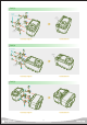
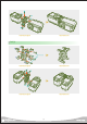
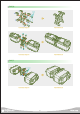
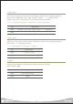
3-3. Connector Pin & System Assembly
Caution
Do not connect the servo directly to the PC without using the Motion Controller or Signal Converter.
Even though both PC and the servo uses serial protocol (TXD, RXD ) they are not directly compatible
due to electrical difference.
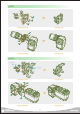
Caution
If using custom made Wire Harness, make sure to check that connector pin assingments are in correct
order. Servo LED will blink once if it is receiving power properly. If the LED does not blink, check the
connector pin assignment and the power supply Voltage and Amp.
Caution
GND
VDD
TXD
RXD
Pin # Description
1
2
3
4
17
Controller
Controller
232 Gender
RS232
Cable
RS232
Cable