
Installation Guide

Installing the LCD monitor M55L AHD, M75L AHD
EN
16
7.3 Connecting the monitor electrically
The circuit diagram for the LCD monitor can be found in fig. d, page 7:
A
Observe the following instructions when laying the connection cable:
•
If possible, use original ducts for laying the cables, or other suitable options, such as ventilation
grilles. If there are no existing ducts, you must drill a hole of ∅ 22 mm. Check beforehand that
there is sufficient space on the other side for the drill head to emerge (fig. 2, page 3).
•
Cover the holes with the feed through (fig. b 1, page 6) in the base of the monitor bracket.
•
To prevent damage to the cables, when laying them ensure that there is always sufficient
distance to vehicle components which can become hot (lights, heaters, ventilators etc.).
•
When laying the cables (fig. 3, page 3), make sure:
– They are not kinked or twisted
– They do not rub on edges
– They are not laid in sharp-edged ducts without protection.
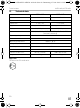
No. Description
1Monitor
220-pin socket
3 Monitor line
4 20-pin plug
5 12 – 24 V positive cable (red): connected to the positive pole of the ignition
(connected positive, terminal 5) or the positive pole of the battery
(terminal 30).
6 Earth cable (black): connected to the negative pole of the voltage source.
7 Cable (green): control input for video input CAM1,
such as for connecting the reversing light
8 Cable (white): control input for video input CAM2,
such as for the side camera
9 6-pin CAM1 socket (connection to video source 1)
10 6-pin CAM2 socket (connection to video source 2)
11 6-pin CAM3 socket (connection to video source 3),
with video signal detection)
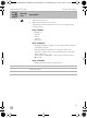
NOTICE!
Cables and connections that are not properly installed will cause malfunctions or
damage to components.
Correct installation of cables and connections ensures lasting and trouble-free
operation of the retrofitted components.
M55L-AHD-M75L-AHD-IO-16s.book Seite 16 Donnerstag, 27. Juni 2019 8:24 20