EN Absorber refrigerator Installation Manual RMDX21, RMDX25
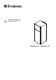
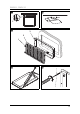
RMDX21, RMDX25 525 mm B 622 mm 2 2 3 1 4 2 550 mm 1264 mm A 1245 mm 1
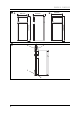
RMDX21, RMDX25 3 < 1250 ≥ 1250 1 4 10 - 40 >40 >40 3
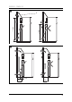
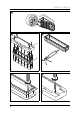
RMDX21, RMDX25 5 ≥ 1400 1 10 - 40 6 4 1 ≥ 300 2
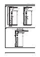
RMDX21, RMDX25 7 8 ≥ 40 mm 1 9 3 2 1 0 a 5
RMDX21, RMDX25 b 2. 3. 1.
RMDX21, RMDX25 g 1 2 3 10 4 5 6 9 6 7 8 h i 1. 1. 3. 2. min. 15 mm 2.
RMDX21, RMDX25 j k 1 2 507,5 507,5 ≤ 36 B 1, 7 A 300 l 1, 7 99,5 ≤ ≤ 36 300 507,5 1, 7 907,4 99,5 8
RMDX21, RMDX25 m 3. 2. 4. 1.
RMDX21, RMDX25 n 1. 2. 10 4. 3.
RMDX21, RMDX25 o 2. 3. 1.
RMDX21, RMDX25 p 1. 2. 3.
RMDX21, RMDX25 r 1. 2. 3.
RMDX21, RMDX25 t 3 1 2 LN N L TO GV 12VDCOUT TO FC 14 TOP AC IN OUT L N N L 15 4 ABS 12 11 5 13 HE OUT 12 VDC HE IN sw vt ws (-) (+) D+ S+ rt ws br br br rt ws (+) (-) (+) (-) 6 9 A G 8 16 rt/vt (+) 10 7 (-) (+) D+ (+) (-) B C D E F 14 sw
RMDX21, RMDX25 Item Description 1 Heating cartridge AC power 2 AC power connection cable 3 Earth AC power 4 Ionisation 5 Ignition 6 Burner 7 Heating cartridge DC power supply 8 Heating cartridge DC power 9 LED lighting 10 Electronics DC power supply 11 Gas inlet 12 Gas outlet 13 Gas valve 14 DC power outlet 15 Gas valve supply line 16 Switch-off fuse (overheating protection) A Optional connections to DC power outlet B Negative terminal (–) DC permanent supply for electro
RMDX21, RMDX25 u v Refrigerator DC connections AES D+ Control D C + B - Element DC E + F - House Battery Anderson Plug Anderson cables must be the recommended size. Refrigerator DC connections w AES D+ D Control C + B - Element DC E + House Battery Anderson Plug Vehicle Anderson plug must be controlled by ignition relay. 16 Anderson cables must be the recommended size.
RMDX21, RMDX25 Refrigerator DC connections x AES D+ D Control C + B - Element DC E + F - Fridge Switch House Battery Anderson Plug Vehicle Anderson plug must be controlled by ignition relay. Anderson cables must be the recommended size. Refrigerator DC connections y AES D+ D Control C + B - Element DC E + F - Fridge Switch House Battery Anderson Plug Vehicle Anderson plug must be controlled by ignition relay. Anderson cables must be the recommended size.
Explanation of symbols RMDX21, RMDX25 Please read this instruction manual carefully before installation and first use, and store it in a safe place. If you pass on the product to another person, hand over this instruction manual along with it. I NOTE You can find details on the operation in the operation manual. Table of contents 1 Explanation of symbols . . . . . . . . . . . . . . . . . . . . . . . . . . . . . . . . . . 18 2 Safety instructions . . . . . . . . . . . . . . . . . . . . . . . . . . .
RMDX21, RMDX25 2 Safety instructions Safety instructions The manufacturer accepts no liability for damage in the following cases: Faulty assembly or connection Damage to the product resulting from mechanical influences and excess voltage Alterations to the product without express permission from the manufacturer Use for purposes other than those described in the operating manual ! WARNING! Never open the absorber unit. It is under high pressure and can cause injury if it is opened.
Safety instructions A RMDX21, RMDX25 NOTICE! Only hold the refrigerator at the body of the refrigerator during transport. Never hold the refrigerator at the absorber unit, the cooling fins, the gas pipes, the door or the control panel. Make sure that the refrigerator circuit is not damaged during transportation. The refrigerant in the refrigerator circuit is highly flammable. In the event of any damage to the refrigerator circuit (smell of ammonia): – Switch off the refrigerator if applicable.
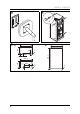
RMDX21, RMDX25 3 Scope of delivery Scope of delivery Refrigerator Ice-cube tray Operating manual Installation manual 4 Accessories Available as accessories (not included in the scope of delivery): Description LS300 ventilation grille 3776 gas exhaust vent All the accessories are available from specialist dealers. If you have any questions, please contact the dealer or your service partner directly.
Installing the refrigerator 6 Installing the refrigerator 6.1 Preparing the installation RMDX21, RMDX25 When installing the refrigerator, note the following: To enable the refrigerant to circulate properly, the refrigerator may not exceed an angle of 3° from level. To achieve this, park the vehicle on a level firm surface. Ensure the refrigerator is level.
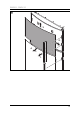
RMDX21, RMDX25 Installing the refrigerator If the minimum distance between the air inlet and outlet vents cannot be met, a roof vent must be installed instead of the air outlet vent. – The roof vent should be installed directly above the back of the refrigerator as far as this is possible. Use an air duct (fig. 5 1, page 4) if you need to install the roof vent offset, otherwise heat will accumulate there. – The distance between the air inlet vent and the roof vent must be at least 1400 mm (fig.
Installing the refrigerator 6.2 RMDX21, RMDX25 Installing the refrigerator in a sealed location separate to the living space Gas-powered refrigerators in caravans or motorhomes must be installed in a sealed location. This means that the combustion air can not be extracted from the interior and exhaust fumes are prevented from directly entering the living space. A suitable seal must be provided and fitted between the rear wall of the refrigerator cabinet and the interior of the vehicle.
RMDX21, RMDX25 Installing the refrigerator 6.3 Making air inlet and outlet vents I NOTE At high ambient temperatures, the refrigerator can only provide its maximum cooling capacity if the optimum ventilation has been provided. ➤ Make a cut out in the wall to fit an appropriate upper and lower vent system, choose LS300 check the dimensions required for the vent. See chapter “Preparing the installation” on page 22.
Installing the refrigerator 6.4 RMDX21, RMDX25 Installing the ventilation grille No. in fig. 9, page 5 Description 1 Slider 2 Ventilation grille 3 Installation frame ➤ Ensure the installation frame is water resistant (fig. 0, page 5). ➤ Insert the installation frame and screw it down tightly (fig. a, page 5). Use all the fixing holes for this. ➤ Fit the ventilation grille (fig. b, page 6). ➤ Insert the slider and lock the ventilation grille with it (fig. b, page 6). 6.
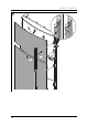
RMDX21, RMDX25 Installing the refrigerator 6.6 Installing the flue duct I NOTE Do not install an additional flue stack, as this leads to poor performance and increases the power consumption of the refrigerator. Mount the flue duct under the upper ventilation grille (fig. g 1, page 7). Install the flue duct as follows: ➤ Make a rectangular opening in the outer wall of the vehicle (fig. h, page 7). – The opening must be as wide as the flue pipe (fig. g 3, page 7).
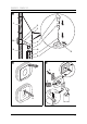
Installing the refrigerator RMDX21, RMDX25 6.7 Securing the refrigerator ! I CAUTION! Only screw through the receptacles provided, otherwise foamed components, including cables, can be damaged. NOTE Attach the side walls or the attached strips so that the screws are tight, even when under increased loads (while driving). ➤ Move the refrigerator into its final location. ➤ Fasten the four screws (fig.
RMDX21, RMDX25 Installing the refrigerator Installing the new door panel and trim on framed door model Proceed as follows (fig. n, page 10): ➤ Push the new panel upwards in the door as far as the stop. ➤ Push the new panel downwards into the door. ➤ Pull the new panel into the door trim still installed. ➤ insert the door trim again. ✓ The door trim is secure once it clicks into place. Removing the door panel from frameless door model Proceed as follows (fig.
Connecting the refrigerator RMDX21, RMDX25 7 Connecting the refrigerator 7.1 Connecting to the gas supply A NOTICE! This refrigerator may only be connected to the gas supply by a specialist in accordance with the applicable guidelines and standards. Only use cylinders of universal LPG gas fitted with an approved gas pressure regulator. Compare the pressure information on the data plate with the pressure information on the pressure regulator on the gas cylinder.
RMDX21, RMDX25 Connecting the refrigerator 7.2 Connecting to DC and AC A NOTICE! The electrical installation and repairs may only be performed by a specialist in accordance with the applicable regulations and standards. The respective negative and positive cables of the DC connections for heating and controls may not be joined with one another in a caravan. This can cause electrical interference or damage to electrical components.
Connecting the refrigerator RMDX21, RMDX25 ➤ Connect the refrigerator as follows (fig.
RMDX21, RMDX25 Connecting the refrigerator AC power ➤ Connect the refrigerator with the mains plug to an AC socket. DC power Please note the following cable sizes: – < 6 m (interior): 6 mm2 – > 6 m (interior): 10 mm2 – Connections D+ and S+: 1 mm2 ➤ Protect the DC power supply for heater with 20 A fuse and use a minimum of 6 mm low voltage cable. ➤ Protect the DC power supply for controls with 2 A fuse and use a minimum of 1 mm low voltage cable.
Connecting the refrigerator RMDX21, RMDX25 S+ (RMDX25 only) In automatic mode, the refrigerator is first powered with DC power from the vehicle's own solar system. The refrigerator electronics uses the S+ signal of the solar charge controller to detect a solar system. The solar charge controller must have an AES output and produce sufficient current to run the refrigerator. ➤ Connect the S+ connection on the controller (fig. t G, page 14) to the respective terminal of the solar charge controller.
RMDX21, RMDX25 Technical data See fig. y, page 17 Using a fridge movement switch to add 12 Vg to the D+ connection wire, only when the vehicle is moving. The Anderson plug connection must keep the house battery fully charged. House battery recharged by vehicle. The D+ is turned on and off via an optional fridge movement switch. See fig. z, page 17 Anderson plug recharging the house battery via a power diode. The D+ wire can only get a 12 V signal when the battery is being charged.
AUSTRALIA Dometic Australia Pty. Ltd. 1 John Duncan Court · Varsity Lakes QLD 4227 1800 212121 · +61 7 55076001 Mail: sales@dometic.com.au AUSTRIA Dometic Austria GmbH Neudorferstraße 108 A-2353 Guntramsdorf +43 2236 908070 +43 2236 90807060 Mail: info@dometic.at ITALY Dometic Italy S.r.l. Via Virgilio, 3 I-47122 Forlì (FC) +39 0543 754901 +39 0543 754983 Mail: vendite@dometic.