INSTALLATION AND OPERATING INSTRUCTIONS REFRIGERATOR FOR LP-GAS AND ELECTRIC OPERATION RA/RM-1D FOR YOUR SAFETY RM2350 If you smell gas: 1. Open windows and door. 2. Don’t touch electrical switches. 3. Extinguish any open flame. 4. Immediately call your gas supplier. FOR YOUR SAFETY Do not store or use gasoline or other flammable vapors and liquids in the vicinity of this or any other appliance.
contents Introduction We are pleased that you have chosen this refrigerator and hope you will derive much satisfaction from using it. The refrigerator is designed for storage of foods and storage of frozen foods and making ice. The installation and servicing should only be carried out by an authorized/qualified person. It is important to read through these instructions carefully before using the refrigerator.
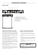
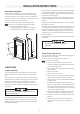
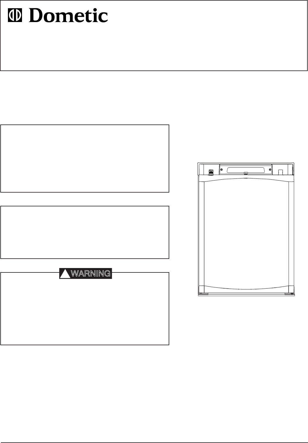
refrigerator overview Control panel A E D C A. B. C. D. E. B ON/OFF, Fuel selector switch Thermostat knob, Gas/Electric Flame failure safety valve push-button Piezo igniter Flame indicator General advice and information Absorption refrigerator system In an absorption refrigerator system, ammonia is liquefied in the finned condenser coil at the top rear of the refrigerator.
Installation instructions The installation, servicing and gas installation must be performed by an authorised/qualified person. The refrigerator must be installed in accordance with the manufacturers installation instructions, local gas fitting regulations, municipal building codes, electrical wiring regulations, AS5601 “Gas Installations” and any other statutory regulations.
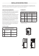
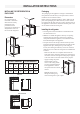
Installation instructions Installing the refrigerator in enclosure Packaging Dimensions It is essential that all maximum or minimum dimensions are strictly maintained, as the performance of the refrigerator is dependent on adequate flow of air over the rear of the refrigerator. Condenser Minimum ventilation height Installing the refrigerator • The refrigerator must be installed in a substantial enclosure and must be level. • Note! Do not install the appliance directly on carpeting.
Installation instructions All connectors etc. should be of a type specifically designed for the type and diameter of the connection pipe used, and screwed joints should be sealed with a joining compound approved for use with bottle-gas. The gas supply pipe should be connected to the gas valve at the top of the refrigerator, by means of a suitable threaded coupling. The gas valve is furnished with an ISO 7/1 - Rp 1/8 internal pipe thread connection.
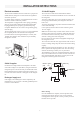
Installation instructions Electrical connection 12 Volts DC Supplies The connection is made to the terminal block marked “12 volts DC” located at the bottom left corner on the back of the refrigerator. To avoid a voltage drop, the cross sectional area of the connecting wires between battery and refrigerator must be at least 6 mm2. To ensure safe operation, the positive lead must be fitted with a fuse rated at 20 amps. Correct polarity must be observed when connecting to the 12 V DC supply.
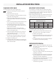
Installation instructions CHANGING DOOR SWING MOUNTING THE DOOR PANEL To change the door swing to the opposite side: 1. Remove the top hinge pin and lift out the door. Save the pin. 2. Remove the lower hinge pin. 3. Move the hinge pin to the hinge bracket on the opposite side of the refrigerator. 4. Remove the hinge bushing and the latch retainer on the top of the door. Save the screw to the latch retainer. 5. Take a new hinge bushing and latch retainer (from the parts bag placed inside the refrigerator).
operating instructions GAS, AC and DC operation REGULATING THE TEMPERATURE The refrigerator is equipped with a thermostat that can be adjusted by turning the knob B to different setting to maintain the desired cabinet temperature. Gas operation • At “OFF, the thermostat closes its main valve and the burner runs continuously at the bypass rate, just enough to keep the burner lit. • At “MAX”, the thermostat allows the burner to remain on high flame continuously.
operating instructions Storage compartments Product care Defrosting ! WARNING 1. Shut off the refrigerator by turning the knob A to “OFF” position. 2. Empty the refrigerator, leaving the drip tray under the finned evaporator. 3. Leave the cabinet and freezer doors open. Filling the ice tray with hot water and placing it on the freezer shelf can reduce defrosting time. Do not store explosive substances in the refrigerator, such as cigarette lighter gas, gasoline, ether or the like.
Maintenance & service Service and maintenance must be done on a regular schedule to keep the refrigerator operating properly, efficiently and safely. The service should only be performed by a qualified technician who is familiar with LP gas systems and refrigerators. Replacing the heater Cleaning the flue and burner Inspect the flue baffle. It should be reasonably clean and free of soot. Heavy soot formation indicates improper functioning of the burner.
Maintenance & service 14. Check to make sure the slots are centred under the flue tube and that the thermocouple is positioned properly (tip of thermocouple extends over two slots of burner). Note that the colour of the flame should be clear blue over the slots of the burner. Troubleshooting Refrigerator does not cool properly • Burner jet clogged. • Check level of refrigerator. Clear blue colour of flame • Venting problem. • Heavy frost buildup on evaporator fins.
Appendix A - RemovING and replacing THE shelves General instruction. The number of shelves and position may vary between different refrigerator models. Put a screwdriver into the slot of the shelf lock. Turn the screwdriver counterclockwise. Remove the shelf locks from the wire shelf. Insert the ends of the wire shelf on the left-hand side at the desired position. Slide the wire shelf to the left. The right-hand side of the shelf will come loose. Slide the shelf into the holes on the right-hand side.
Appendix B - Rearview equipment Heaters Flue baffle 12 volt terminal block Screw for burner cover Burner jet Flexible cord 14
Appendix C - wiring diagram 15