
User manual


7
The supply pipe should preferable be of copper. If other
material is used, it must be of a type approved for use
with continuously operating bottle-gas appliances and
have threaded connections throughout.
All connectors etc. should be of a type specifically de-
signed for the type and diameter of the connection pipe
used, and screwed joints should be sealed with a join-
ing compound approved for use with bottle-gas.
The gas supply pipe should be connected to the gas
valve at the top of the refrigerator, by means of a suit-
able threaded coupling.
The gas valve is furnished with an ISO 7/1 - Rp 1/8 in-
ternal pipe thread connection.
In making the connection to the refrigerator, a union gas
cock of an approved bottle-gas type must be incorpo-
rated in the supply line in a position which is readily ac-
cessible to the user. For eventual servicing purposes,
the union should be positioned so as not to prevent the
refrigerator from being readily withdrawn.
All completed connections should be checked for leaks
with soapy water.
! WARNING
DO NOT use a flame to check for gas leaks.
TESTING LP GAS SAFETY SHUT OFF
The gas safety shut off must be tested after the re-
frigerator is connected to the LP gas supply.
To test the gas safety shutoff, proceed as follows:
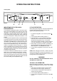
1. Start the refrigerator according to the instructions
for Gas Operation. See section Operating Instruc-
tions.
2. Check that the gas flame is lit. This can be ob-
served on the flame indicator E. The red indicator
is in the green field, (ON).
3. Close the gas valve by turning the knob A back to
OFF position.
4. Wait for one minute.
5. Remove burner cover plate. (See fig. 1).
Open the gas valve by turning knob A to position
(GAS) without pushing the buttons C and D. Apply
a non-corrosive commercial bubble solution to the
burner jet.
6. No bubbles should appear at the opening of the
burner jet. The presence of bubbles indicates a
defective gas safety shutoff, and service is re-
quired.
7. If no bubbles were present at the burner jet, the
gas safety valve is working properly. Rinse jet
thoroughly with fresh water before proceeding. Be
careful not to damage the burner jet.
Replace cover and turn the main switch OFF and
back ON. See instruction for Gas Operation,
section Operating Instructions. Normal operation of
the burner should return. Allow the burner to
operate for a minimum of 5 minutes.
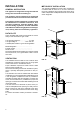
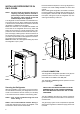
ELECTRICAL CONNECTION
The electrical installation must be carried out in a proper
and durable manner, taking into account all relevant regu-
lations and codes of practice.
For mains voltage operation, it is important that the
circuit to and in the caravan is effectively earthed.
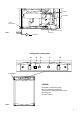
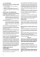
The refrigerator is equipped with a three-prong
(grounded) plug for protection against shock hazards
and should be plugged directly into a properly grounded
three-prong receptacle. DO NOT cut or remove the
grounding prong from this plug. The free length of the
cord is 6 ft. (1,8 m) and therefore recommended that the
receptacle be located to the left side of the refrigerator
(viewed from the rear) and approximately 4-6 inches
(100-150 mm) from the floor (see FIG. 8). This allows
easy accessibility through the vent door.
230-240 Volts Supplies
Check that the voltage stated on the data plate is the
same as the main voltage in use (230-240 V).
Plug the 230-240 V refrigerator power cord into an eas-
ily accessible wall socket.
Electrical leads must be routed and secured so that
they cannot come into contact with hot or sharp parts
of the refrigerator.
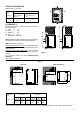
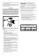
12 Volts DC Supplies
The connection is made to the terminal block marked
12 volts DC located at the bottom left corner on the
back of the refrigerator.
To avoid a voltage drop, the cross sectional area of the
connecting wires between battery and refrigerator must
be at least 6 mm
2
.
To ensure safe operation, the positive lead must be fit-
ted with a fuse rated at 20 amps.
Correct polarity must be observed when connecting to
the 12 V DC supply.
DO NOT use the body or chassis of the vehicle as a
substitute for either of the two conductors.
FIG. 8
230-240 Volt AC
receptacle
4 - 6
(100-
150 mm)