
Troubleshooting guide


INTRODUCTION Eskimo Ice Installation & Operation Manual
4 L-3040 ENGLISH
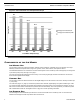
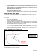
Figure 3: Ice Production and Temperature Graph
COMPONENTS OF THE ICE MAKER
ICE-MAKING UNIT
The ice-making unit has an R-404A compressor, seawater-cooled condenser, a filter/drier, and an accumulator. The auger
assembly contains the evaporator barrel, auger rotor, gearbox, motor, water reservoir, and expansion device.
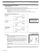
The freshwater delivered to it is converted to ice which exits the system via an ice-delivery hose routed properly to a storage box
up to 35 feet (10.6m) away. See Figure 4 on page 7.
The unit is pre-charged with refrigerant from the factory. The unit has plug-and-play electrical connections for the ice-level
sensor and the optional remote display.
CONTROL BOX
The ice-making unit has an electrical control box with digital display that can be mounted on the unit or remotely mounted up to
7’ (2.1m) away.
The control box (Figure 11, page 14) contains the system function switches, digital display, and system indicator lights. It lets
you control all system operations and provides visual indications of system activity, such as whether the system is running or
has a fault. If a fault condition is detected, the system shuts down automatically. The control panel lets you restart the system
after a sustained fault. See the “The Digital Control” on page 14 for further operating instructions.
ICE-STORAGE BOX
The ice-storage box is the destination point where the ice will accummulate via the ice-delivery hose. An ice-level sensor
installed in the storage box halts ice production when the box is full.
25.8
23.9
20.9
17.8
16.9
14.3
620
573.6
501.6
427.2
405.6
343.2
50°
60°
70°
80°
90°
100°
Fresh Water Temperature (F)
Average Ice Production/hr
Average Ice Production/24hr
Pounds of Ice