Eskimo Ice Crushed Ice System Installation & Operation Manual FOR MODEL EI540D USING DIGITAL CONTROLS (WITH C-19 SOFTWARE) EI540D Digital Display Optional Remote Display Dometic Group Marine Division Rev. 20140910 L-3040 English P/N 336124 COPYRIGHT © 2008-2014 Dometic Group Marine Division. All Rights Reserved.
Table of Contents INTRODUCTION . . . . . . . . . . . . . . . . . . . . . . . . . . . . . . . 1 PROGRAMMABLE PARAMETERS FOR SOFTWARE 18 WARNINGS AND NOTICES . . . . . . . . . . . . . . . . . . . . . . 1 PROGRAM PARAMETER DESCRIPTIONS . . . . . . . . . . . 18 ICE MAKING AND REFRIGERATION BASICS . . . . . . . . . . 2 How Ice Is Made . . . . . . . . . . . . . . . . . . . . . . . . 2 The Refrigeration Process . . . . . . . . . . . . . . . . 2 PROGRAM PARAMETER DEFAULT SETTINGS . . . . . . .
Eskimo Ice Installation & Operation Manual INTRODUCTION INTRODUCTION This manual provides installation and operation information for the EI540D self-contained Eskimo Ice System using digital controls (software level C-19). The ice produced by this system is not potable and should not be ingested. Do not eat, chew, suck, swallow, or put the ice into drinks. The ice produced by this system is intended solely for the refrigeration purposes of freshly caught fish stored in a fish box.
INTRODUCTION Eskimo Ice Installation & Operation Manual ICE MAKING AND REFRIGERATION BASICS Figure 1: Ice-Making Process HOW ICE IS MADE Fresh water is applied to the interior wall of the evaporator shell. Using a refrigeration process, heat is removed from the fresh water in order to freeze it. As the water freezes onto the wall of the evaporator shell, the auger scrapes it off and into a discharge port.
Eskimo Ice Installation & Operation Manual INTRODUCTION Figure 2: Refrigeration System Diagram THE EFFECT OF TEMPERATURE ON ICE PRODUCTION WATER TEMPERATURES Seawater and freshwater temperatures affect the ice machine’s efficiency and capacity. The system is most efficient when the seawater and fresh water temperatures are 55-80°F (13-27°C). The ideal temperature for both is 70°F (21.1°C). See Figure 3.
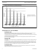
INTRODUCTION Eskimo Ice Installation & Operation Manual Figure 3: Ice Production and Temperature Graph 620 573.6 501.6 Pounds of Ice 427.2 405.6 343.2 Average Ice Production/hr Average Ice Production/24hr 25.8 23.9 50° 20.9 60° 70° 17.8 80° 16.9 90° 14.3 100° Fresh Water Temperature (F) COMPONENTS OF THE ICE MAKER ICE-MAKING UNIT The ice-making unit has an R-404A compressor, seawater-cooled condenser, a filter/drier, and an accumulator.
Eskimo Ice Installation & Operation Manual INTRODUCTION The ice-storage box should be able to hold water and have at least 2" (51mm) of insulation to keep the ice frozen as long as possible. It is helpful to install a drain in the box at the end opposite from the ice input. To improve ice-production performance, keep the drain plugged to prevent cold air and cold water from escaping the storage box.
INSTALLATION PROCEDURES Eskimo Ice Installation & Operation Manual INSTALLATION PROCEDURES This section covers the installation procedures for your ice-making system. Read the manual completely before attempting to install any equipment. CHOOSING THE CORRECT EQUIPMENT VOLTAGE Know the frequency and voltage provided where your ice-making system will be used and select the appropriate 60 Hz or 50 Hz model.
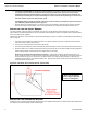
Eskimo Ice Installation & Operation Manual INSTALLATION PROCEDURES INSTALLING ICE-DELIVERY HOSE Planning the Route The maximum length of the ice-delivery hose is 35 feet (10.6 m) under ideal conditions. The best hose routing provides a level but slightly upward rise from the ice maker to the ice-storage box, with very few bends. No bend should be tighter than a radius of 18" (458mm). Refer to Figure 4 below to see: • Best Routing - A continuous uphill route of travel from the ice maker.
INSTALLATION PROCEDURES 6. Eskimo Ice Installation & Operation Manual The EI540D now REQUIRES a Constant Torque Hose Clamp to secure the ice delivery hose to the auger spout. It is supplied with the machine and attached to the Auger spout with a black wire tie. The clamp must be installed behind the 8 protruding dimples on the auger ice spout. The use of another type of clamp will void the warranty and liability of ice overflow and damage if the hose comes off while producing ice.
Eskimo Ice Installation & Operation Manual INSTALLATION PROCEDURES Requirements • Supplied feedwater must have a pressure of at least 15 PSI. • The water system must be able to supply at least 4 GPH when the ice maker is operating. • Install the in-line filter (supplied in kit) just prior to the unit to remove sediment which may clog the needle valve in the water reservoir.
INSTALLATION PROCEDURES Eskimo Ice Installation & Operation Manual Figure 7: Seawater Piping Recommendations Thru-Hull Inlet Fitting A separate thru-hull fitting must be installed for each seawater pump. Do not attempt to draw water from the thru-hull fitting of an engine, generator, or other device. Install a scoop-type thru-hull fitting: 1. Drill a properly sized hole for the thru-hull fitting as far below the water line and as close to the keel as possible. 2.
Eskimo Ice Installation & Operation Manual INSTALLATION PROCEDURES • Use the correct size hose, fittings, and components: 5/8” seawater hose, 3/4” inlet. Note that the pump inlet piping (including thru-hull and strainer) may need to be larger than the outlet pipe size. Do not use pump connections to determine hose size. • The "pump inlet" recommended pipe size includes all fittings and hose up to the pump connection (thru-hull, seacock, strainer, hose, manifold).
INSTALLATION PROCEDURES Eskimo Ice Installation & Operation Manual Figure 9: Seawater Manifold Orientation Pump Relay The pump relay (if needed) is generally located in the engine room or mechanical space near the seawater pump, but can be mounted anywhere that is convenient and accessible. It must be in a dry location, away from water spray, with some room for heat dissipation. Choose your pump relay based on the number of units that will operate off one pump.
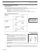
Eskimo Ice Installation & Operation Manual 1. Find a convenient location that is protected from saltwater spray. 2. Cut out a square hole that is 3-3/16” x 3-3/16” (82 x 82 mm). See Figure 10 to prepare the mounting space. 3. Route the display’s cable to control box and plug into the mating 8-pin male RJ45 connector. 4. Mount the remote display into the cutout. 5. If you are relocating the existing display, cover the hole on the back of the box.
OPERATION Eskimo Ice Installation & Operation Manual OPERATION This section of the manual provides the essential information for safe operation for all Dometic ice makers. If you encounter any operational problems, call your dealer or the Dometic Marine Service Department at 954-973-2477. WARNING Failure to install and use the water filter included with the installation kit will void the warranty. Note, if unit is purchased separately you must also purchase the water filter to maintain warranty.
Eskimo Ice Installation & Operation Manual OPERATION BASIC FUNCTIONS APPLYING POWER When power is first applied, the display will light all LED’s for 2 seconds, then go blank for 1 second, then show software revision for 2 seconds. The unit will then go to the last state it was in before power was disconnected. The power LED will remain lit anytime power is applied. ON/OFF Press the On/Off button to toggle between Off and ICE production.
OPERATION Eskimo Ice Installation & Operation Manual default. HPF can be caused by lack of seawater flow due to a dirty strainer, pump being airlocked or seawater lines in need of maintenance. LAC – LOW AC LINE VOLTAGE If the line voltage to unit is less than value selected in the programmable parameter for 5 minutes continuously the unit will stop operation.
Eskimo Ice Installation & Operation Manual THE CYCLE OF OPERATION OPERATION Figure 12: Typical Operation Cycle For Making Ice Refer to list of faults in this manual to see which faults automatically reset once the particular switch resets, and which faults must be cleared manually.
PROGRAMMABLE PARAMETERS FOR SOFTWARE Eskimo Ice Installation & Operation Manual PROGRAMMABLE PARAMETERS FOR SOFTWARE The programmable parameters with their factory defaults described in this section. Table on page 18 contains the parameter codes along with their permitted values and default settings. Parameters P1 / t-1 through t-5 are user adjustable parameters. Checking Software Revision Level To confirm software revision, first turn off power to unit.
Eskimo Ice Installation & Operation Manual STARTING THE SYSTEM STARTING THE SYSTEM START-UP CHECK LIST Before you start the system: • Confirm freshwater supply is on. • Confirm freshwater filter is installed. • Confirm that electrical connections are correct and tight. • Confirm that the circuit breaker is of the correct size. • Confirm the ice-level sensor is mounted securely, the cable is routed safely, and the sensor is functioning properly. • Confirm all units are mounted securely.
SERVICING THE SYSTEM • Eskimo Ice Installation & Operation Manual Turn the unit’s circuit breaker off then on. SERVICING THE SYSTEM This section contains information critical to correct servicing of this Dometic ice-making system. Read and understand all information before beginning. If you have any questions, call the Dometic service department at 804-746-1313. REFRIGERANT Your Dometic ice-making system contains R-404A refrigerant, an environmentally safe gas.
Eskimo Ice Installation & Operation Manual OWNER MAINTENANCE OWNER MAINTENANCE The periods and procedures given for maintenance and cleaning are guides only and should not to be construed as absolute or invariable. Cleaning frequency will vary depending on local water conditions (hard water, etc.) and the ice volume produced. SEAWATER SYSTEM Check the seawater strainer daily and remove any debris.
TROUBLESHOOTING GUIDE Eskimo Ice Installation & Operation Manual COMPRESSOR The compressor has no user-serviceable parts, and is lubricated constantly during operation. REFRIGERANT GAS The refrigerant included in the system is adequate for the life of the system and should not need routine or seasonal charging. If the need exists for routine charging, have your dealer look for a refrigerant leak that needs repair.
Eskimo Ice Installation & Operation Manual PROBLEM Feedwater fault. (H2O) TECHNICAL ASSISTANCE POSSIBLE REASONS & SOLUTIONS 1. Check water pressure in boat’s potable water system. 2. Check for a supply valve that has been turned off. 3. Check for a clogged feedwater filter. 4. Check for a cloged Y strainer located on the feedwater line of the unit. 5. Check for a clogged needle valve in the water reservoir. Ice delivery volume seems less or slower. 1. High seawater temperature. 2.
DIAGRAMS Eskimo Ice Installation & Operation Manual DIAGRAMS SYSTEM CONNECTION Figure 13: Diagram of System Components and Water Flow Figure 14: EI540D Connection Locations Seawater Out Fresh Water In Electrical Box Wire Ice Outlet Seawater In Drain 24 L-3040 ENGLISH
Eskimo Ice Installation & Operation Manual DIAGRAMS ELECTRICAL WIRING FOR 115V 60 HZ MODELS Figure 15: Wiring Diagram for 115V 60Hz Models L-3040 ENGLISH 25
DIAGRAMS Eskimo Ice Installation & Operation Manual ELECTRICAL WIRING FOR 230V 60 HZ MODELS & 220V 50 HZ MODELS Figure 16: Wiring Diagram for 230V 60Hz Models and 220V 50 Hz Models 26 L-3040 ENGLISH
Eskimo Ice Installation & Operation Manual OWNERS LIMITED WARRANTY OWNERS LIMITED WARRANTY As hereinafter described, Dometic limits the duration of any implied warranty to the duration of the underlying express warranty and also disclaims any liability for consequential or incidental damages arising from any application, installation, use or malfunction of any warranted product.
OWNERS LIMITED WARRANTY Eskimo Ice Installation & Operation Manual 13. Liquid line filter dryers are not covered. 14. Logic boards with water damage. 15. Logic boards with blown MOV's (Power Surge) 16. Mis-programmed displays. 17. Display heads with water damage. 18. Dirty condensers and/or evaporators. 19. Failures due to improper winterization. 20. Unit damage as a result of improper return packaging. 21. Replacement of freon with substitute without authorization from factory. 22.
Eskimo Ice Installation & Operation Manual TABLE OF OWNERS LIMITED WARRANTY WARRANTY PERIODS DOMETIC - ESKIMO ICE CRUSHED ICE SYSTEMS Important Notes: 1. Warranty periods begin from the date of possession of the boat by the first owner if OEM installed or date of installation if dealer installed, but not to exceed three (3) years from date of production.