Eskimo Ice Remote Ice Crushing System Installation & Operation Remote Ice Crushing System Revised: 6-21-06 L-2448B
TABLE OF CONTENTS Maintenance INTRODUCTION Seawater System .............................................................. 11 Refrigerant Gas ................................................................ 11 Compressor ...................................................................... 11 Auger Motor ...................................................................... 11 Auger Gearbox ................................................................. 11 Water Reservoir ...............................
INTRODUCTION Drawings and Diagrams WARNING The figures, drawings, or diagrams that are referenced in this manual can be found directly after the warranty section. In addition, some equipment may be shipped with specific installation sheets or wiring diagrams that may supercede the information located in this manual. Dometic reserves the right to update or change any information located herein at any time and without prior notice.
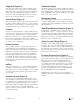
Auger Unit (Figure 2) Freshwater Supply The auger unit contains the evaporator barrel, auger rotor, gearbox, motor, water reservoir, and expansion device. The unit comes with quick connect refrigerant fittings and is pre-charged with refrigerant from the factory. The unit has plug-and-play electrical connections to the control box and the ice level sensor. Freshwater supply for ice making should be provided via the ¼" male flare fitting on the auger unit. Provide water with pressure of at least 15 PSI.
INSTALLATION This section covers installation procedures for your ice making system. Please read the manual completely before attempting to install any equipment. Use screws or bolts through the holes in the four corners of the pan to secure the unit. You may remove the pan and turn to get the proper orientation of the drain stub.
Installing the Ice Level Sensor Connecting the Quick Connect Fittings Use Figure 5 to determine placement for the Ice Level Sensor. The sensor must be located below the ice delivery hole and to the side, per Figure 5. Drill 23/32" hole for sensor. Use two lock nuts provided to secure sensor into hole. Use marine grade sealant around the hole if desired. Remember that the unit may have to be removed at some time. Route the cable to the auger unit, and plug into the matching plug.
on the unit. Ensure that there are no leaks in the field installed portion of the system. The water reservoir has a float switch to ensure that the unit does not operate without water supply. without any dips of loops, and with only one high point in the system. This is called self-draining because all the water will drain out of the piping if the boat were taken out of the water. Whenever air gets into the system, which can happen in heavy seas or a sharp turn, it can become trapped in the pump.
Seawater Pump • Use the correct size hose, fittings, and components. See Figure 9 for proper sizing. Note that the pump inlet piping (including through-hull and strainer) may need to be larger than the outlet pipe size. Do not use pump connections to determine hose size. Centrifugal pumps are not self-priming, and must be mounted so that they are below the heeled waterline in any given operating condition. The pump should be accessible for future service.
OPERATION This section of the manual refers to essential safe operation for all Dometic ice makers. For any operational problems, call your dealer, or our service department at 804-746-1313. • Watch for ice within five minutes of starting, plus approximately one minute for each foot of hose between the box and auger unit NOTE: The seawater pump should cycle automatically whenever the unit is running. Regularly check for seawater flow by observing the overboard discharge.
Servicing the System This section contains information critical to correct servicing of this Dometic ice making system. Please read and understand all information before beginning. If you have any questions, please call Dometic at (804) 746-1313. Refrigerant Your Dometic ice making system contains R134a refrigerant, an environmentally friendly gas, which has no current phase-out date. R134a is a single component refrigerant and should never be charged in the liquid phase while the unit is running.
Charging the System 6) Evacuate the system as described in “Evacuate Refrigerant, and recharge the system with the correct amount of R134a. 1) Remove line from vacuum pump, and connect to a bottle of R134a. The charge should be weighted in by placing the bottle on a refrigerant scale. 7) Set suction pressure as described in “Setting the CPV.” 2) Turn the bottle upside down, and purge the charge hose at the gage set. 3) Allow refrigerant to flow in the high side until the correct charge is reached.
Water Filter Winterizing the System Change the filter at least twice per year, or every 1500 gallons, whichever comes first. The correct filter will help prevent clogging of the float valve, and scale buildup within the evaporator chamber. We suggest Dometic Part #3150707. Close the seacock and remove the inlet hose from the condensing unit. Allow all water to drain from the system. Loosen the screws on the pump head to allow water to drain from the pump.
Problem: Feedwater fault light on Problem: Oil in auger assembly drain pan Potential solution: Potential Cause/Solution 1) Check for water pressure in boat’s potable water system 1) Water in gear reducer has raised level of the oil so that it can run out of the weep hole on the top of the gear housing. It may occur due to: 2) Check for a valve that has been turned off i. Leaking water seals in the evaporator/auger assembly, replace seals. 3) Check for a clogged feedwater filter.
Owner’s Limited Warranty As hereinafter described, Dometic Environmental Corporation limits the duration of any implied warranty to the duration of the underlying express warranty and also disclaims any liability for consequential or incidental damages arising from any application, installation, use or malfunction of any warranted product.
WARNING The hours of the Customer Service Department are 8:00 am 5:00 pm (USA, Eastern Time Zone) Monday through Friday excluding holidays. Dometic Environmental Corporation (Dometic) manufacturers of Cruisair, Dometic Auxiliary A/C, Dometic Refrigerators and Freezers, Eskimo Ice, Grunert, Marine Air, and Sentry products, makes the following safety warnings concerning the application, installation, use and care of its products.
Limited Warranty Periods Please read and keep this document with your important paperwork. Use it as a reference in the future. If you have any questions, please contact the Dometic Environmental Corporation Service Department at (804)746-1313 for clarification. Note: Any model or replacement part that has been installed due to a warranty failure will carry only the remainder of the original warranty. All warranties begin when the customer takes possession of the equipment.
DESCRIPTION OF FIGURES AND DIAGRAMS Figure 1 – Condensing unit Figure 2 – Auger unit Figure 3 – Control Panel Figure 4 – Constant Pressure Valve Figure 5 – Photoelectric Eye Location Figure 6 – Ice Delivery Hose Routing Figure 7 – Seawater Piping Recommendations Figure 8 – Pump Head Orientation Figure 9 – Seawater Manifold Orientation Figure 10 – Cutout Dimensions for Control Panel Figure 11 – Complete System Hookup Diagram Figure 12 – 120VAC System Wiring Diagram Figure 13 – 240VAC System Wiring Diagram Fi
Figure 1 – Condensing unit Figure 4 – Constant Pressure Valve Seawater Condenser Sight Glass Quick Connects Figure 5 – Photoelectric Eye Location Figure 2 – Auger unit Front View Figure 3 – Control Panel System Running Ice Delivery Fault Feedwater Fault Pressure Fault System Power L-2448B 18 Y English
Figure 6 – Ice Delivery Hose Routing L-2448B 19 Y English
Figure 7 – Seawater Piping Recommendations Figure 8 – Pump Head Orientation L-2448B Figure 9 – Seawater Manifold Orientation 20 Y English
Figure 10 – Cutout Dimensions for Control Panel Figure 11 – Complete System Hookup Diagram L-2448B 21 Y English
Figure 12 – 120VAC System Wiring Diagram L-2448B 22 Y English
Figure 13 – 240VAC System Wiring Diagram L-2448B 23 Y English
Figure 14 – Condensing unit diagram L-2448B 24 Y English
Figure 15 – Auger unit diagram L-2448B 25 Y English
L-2448B 26 Y English
L-2448B 27 Y English
Dometic Environmental Corporation 2000 N. Andrews Ave. Ext. • Pompano Beach, FL 33069-1497 USA • Phone: 954-973-2477 • Facsimile: 954-979-4414 P.O. Box 15299 • Richmond, VA 23227-0699 USA • Phone: 804-746-1313 • Facsimile: 804-746-7248 Website: www.EskimoIceMachine.com • Email: sales@dometicenviro.