
Product Manual

EN
Technical description PS120A, PS180A
8
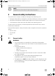
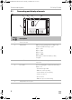
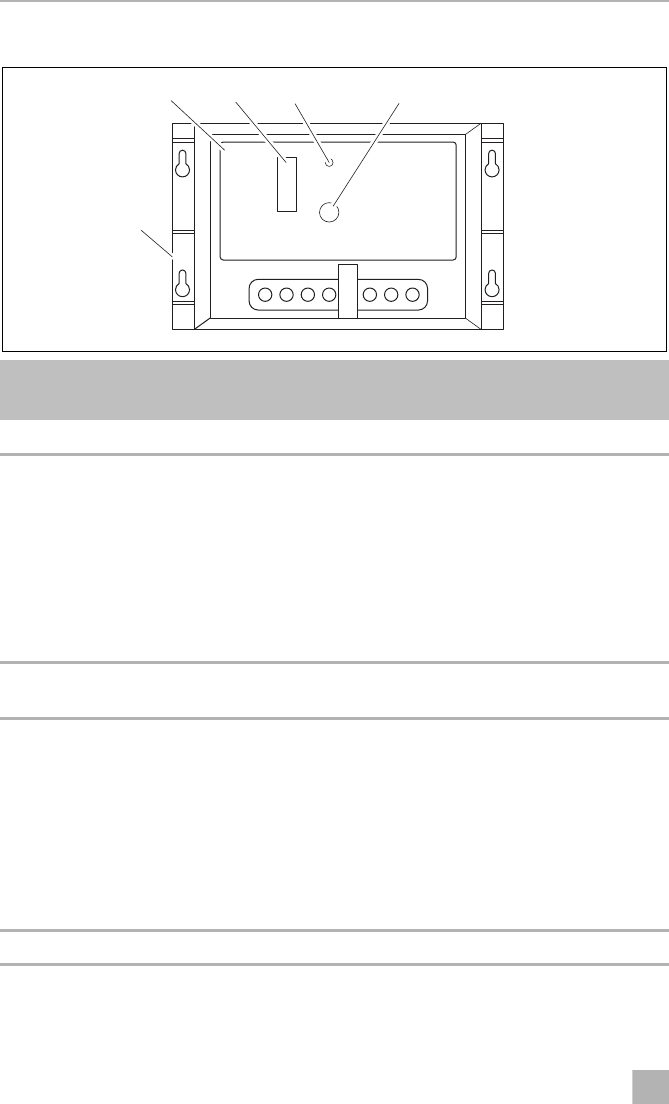
5.1 Connecting and display elements
No. in
fig. 2
Description
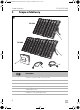
1 Solar controller
2 Status LEDs Battery is being charged according to the
number of LEDs shinning in cycle:
LED 1 = 25%
LED 2 = 50%
LED 4 = 75%
LED 8 = 100%
LEDs light on when the battery is fully
charged.
3 Load LED The output indicator lights on when an output
is present.
4 Error LED The error LED lights on when the following
faults occur:
– Over discharge status
– Batteries reverse polarity
– Solar module reserve polarity
– Load over-current
– Short current
– Batteries open circuit working
5 Temperature sensor port
5
2 3 4
1
2
PS120SolarPanel-O-NZ.book Seite 8 Freitag, 6. Oktober 2017 10:53 10