
Product Manual


EN
Using the appliance PS120A, PS180A
12
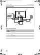
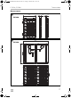
Connecting to a battery
➤ Connect the Alligator clips to the battery terminals. Connect the red lead with
red clamp to the positive (+) battery terminal. Connect the black lead with black
clamp to the negative (–) battery terminal. Ensure that the connection is secure
and tight.
➤ Connect the Anderson plug to the Anderson socket.
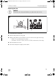
✓ The battery is loading.
✓ The green LEDs on the solar controller light up.
The number of green LEDs show the battery capacity. The LEDs light in cycle dur-
ing charging status. The LEDs stop shinning and light on when the battery is fully
charged. In over-discharge status, LED 1 (25%) flashes quickly to warn the user to
charge the battery immediately.
For safety reasons the solar controller will start buzzing if the battery connection is in
reverse polarity to protect against reversing the polarity and short circuits when con-
necting to a battery.
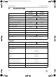
To protect the battery, the solar controller switches off automatically if the voltage is
insufficient (see table below).
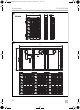
Connecting a 12 Vg device or inverter
➤ Connect the lead to the positive (+) and negative (–) terminal. Ensure that the
connection is secure and tight.
Connecting the temperature sensor
The battery temperature sensor allows the charge controller to continuously adjust
charge voltage based on measured battery temperature.
➤ Attach temperature sensor to the battery with tape, ensuring good contact.
Disconnecting the solar panel
➤ Disconnect the load first, then disconnect the Anderson plug from the solar
panel, finally disconnect the Alligator clips from the battery.
12 V
Switch-off voltage
11 ± 0.3 Vg
Switch-on voltage
12 ± 0.3 Vg
PS120SolarPanel-O-NZ.book Seite 12 Freitag, 6. Oktober 2017 10:53 10