Dolphin™ 6110 Mobile Computer with Windows® Embedded Handheld 6.
Disclaimer Honeywell International Inc. (“HII”) reserves the right to make changes in specifications and other information contained in this document without prior notice, and the reader should in all cases consult HII to determine whether any such changes have been made. The information in this publication does not represent a commitment on the part of HII.
Table of Contents Chapter 1 - Agency Approvals Label Locations ....................................................................................................................1-1 N4313-TTL Safety & RF Approvals by Country: ..................................................................1-1 Dolphin RF Terminal—802.11a/b/g/n and/or Bluetooth .......................................................1-2 Chapter 2 - Getting Started Out of the Box .............................................................
Chapter 4 - Using the Keypad Overview.............................................................................................................................. 4-1 Navigation Keys................................................................................................................... 4-1 Basic Keys........................................................................................................................... 4-1 Alpha/Numeric Modes ...................................................
Task Manager.................................................................................................................... 7-20 Chapter 8 - Communication Connecting the Dolphin 6110-USB Communication Cable ................................................. 8-1 Charging Terminal with USB Cable..................................................................................... 8-1 Connections Menu...........................................................................................................
Parts and Functions........................................................................................................... 11-2 Front Panel .................................................................................................................. 11-2 Back Panel .................................................................................................................. 11-2 Power ...............................................................................................................
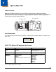
1 Agency Approvals Label Locations Dolphin 6110 mobile computers meet or exceed the requirements of all applicable standards organizations for safe operation. However, as with any electrical equipment, the best way to ensure safe operation is to operate them according to the agency guidelines that follow. Read these guidelines carefully before using your mobile computer.
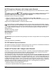
R&TTE Compliance Statement—802.11a/b/g/n and/or Bluetooth Dolphin RF terminals are in conformity with all essential requirements of the R&TTE Directive (1999/5/ EC). 0984 ! in accordance with the Class II product requirements specified This product is marked with in the R&TTE Directive, 1999/5/EC. The equipment is intended for use throughout the European Community; PAN European Frequency Range: 2.402–2.480 GHz.
• Connect the equipment into an outlet on a circuit different from that to which the receiver is connected. • Consult the dealer or an experienced radio/TV technician for help. If necessary, the user should consult the dealer or an experienced radio/television technician for additional suggestions. The user may find the following booklet helpful: “Something About Interference.” This is available at FCC local regional offices.
1-4
2 Getting Started Out of the Box Verify that your carton contains the following items: • Dolphin 6110 mobile computer (the terminal) • Battery pack (3.7v, Li-Ion) • AC power supply (KSAS0100500200D5; Input: 100-240V AC, 50/60Hz 0.4 Amps; Output: 5 Volts DC, 2.0 A) • Localized plug adapters Note: Be sure to keep the original packaging in case you need to return the Dolphin terminal for service; see Customer Support on page 14-1. Initial Setup for Dolphin 6110 Terminals Step 1.
! We recommend use of Honeywell Li-Ion battery packs. Use of any non-Honeywell battery may result in damage not covered by the warranty. Step 2. Charge the Batteries Dolphin 6110s ship with the battery pack significantly discharged of power. Charge the battery pack with the Dolphin charging cable until the LED turns green (red while charging). The average charge time for a fully depleted battery is 7 1/2 hours. It takes less time if the battery has some charge. 1.
The power adapter on the power cable converts the voltage from the power source to 5 volts DC. Only power adapter cables from Honeywell convert the voltage appropriately. The power cable contains a plug adapter for each geography (US, UK, EU, etc.). Plug Adapter Power Adapter Power Cable Step 3. Boot the Terminal The terminal is not connected to an external power source, it begins booting once you push the Power button. If the terminal is connected to an external power source (e.g.
Home Screen After the Dolphin terminal initializes the first time, you see the Home screen. Tap Tap to reach the Start screen from the home screen. to access the Dolphin Wireless Manager Window (see page 8-7) from the home screen. Title Bar The Title bar, located at the top of the screen, displays the active program, the status of various system functions, and the current time. Tapping on the title bar provides access to the Horizontal Scroll.
Horizontal Scroll Indicator Meaning Synchronizing data The terminal could not synchronize data with the workstation via ActiveSync. New e-mail New text message New voicemail New instant message Ringer off A battery error has occurred. Replace the battery pack with a Honeywell Li-poly or Li-ion battery pack. Battery is has a full charge Battery has a high charge Battery has a medium charge Battery has a low charge Battery has a very low charge and requires charging Terminal is running on external power.
Horizontal Scroll The Horizontal Scroll, located at the top of most application windows, provides access to additional application screens. You can flick left or right on the scroll or tap each label on the scroll, until you get to the desired screen. Tapping a label to the left or right of the center item brings new labels into view. Note: Tap the Title bar to access the horizontal scroll if it is not visible on the screen. The content of the Horizontal scroll changes according to the open application.
File Explorer You can also use the File Explorer to find files and organize these files into folders. 1. Tap > File Explorer . 2. Tap the Up button at the bottom of the screen to move up one level in the directory. 3. You can move files in File Explorer by tapping and holding on the item you want to move, then tapping Cut or Copy on popup menu. 4. Navigate to the folder you want to move the file to, then tap and hold a blank area of the window. 5. Tap Paste on the pop-up menu.
File Provisioning on the Dolphin 6110 \IPSM\Honeywell The IPSM folder is the only partition on the terminal that persists across a kernel upgrade (*.UPG file extension). During a kernel upgrade, files are automatically copied from the \IPSM\Honeywell folder and then installed in the \Honeywell (root file system) folder as part of the upgrade process. \IPSM\Honeywell\AutoInstall The files in the IPSM\Honeywell\AutoInstall folder are only installed when a factory reset or kernel upgrade occurs.
Turning Power On/Off To turn the terminal On, press the Power button . To turn the terminal Off: 1. Press and hold the Power button 2. Tap Power off. for approximately 4 seconds until the options menu displays. Suspend Mode Suspend mode differs from Power off mode. Power off mode is the equivalent to having no battery or external power source connected to the device. In Suspend mode, the device enters a low power state to conserve battery power.
2 - 10
3 Hardware Overview Standard Terminal Configurations Dolphin 6110 WPAN/WLAN • Microsoft Windows Embedded Handheld 6.5 Classic • TI OMAP37xx 800MHz • 512 MB RAM X 512 MB Flash Memory • 28-key shifted alpha numeric keypad • 240x320. 262.144 Color Transmissive TFT Display • Standard Capacity: Li-ion battery: 3.7V / 2200mAh / 8.1 Wh or Extended Capacity: Li-ion battery: 3.7V / 3300mAh / 12.2 Wh • 56XX image engine with laser aiming or N4313TTL laser engine • (WPAN/WLAN) - Bluetooth and 802.
Dolphin NetBase Device The Dolphin NetBase device, enables up to four Dolphin 6110 mobile computers to communicate with a host device over an Ethernet network. For more information, see Dolphin 6110 Net Base Device (Model 6100-NB) on page 12-1. USB Communication Cable for the Dolphin 6110 The USB Communication Cable for the 6110 is used when communicating between the terminal and a PC/laptop via the USB port. The cup-style 6110-USB cable slides onto the bottom of the device lining up with the connector.
Scan/Decode LED Note: The LED is user-programmable. LED color Description Red While battery is charging. Once Scan button pressed in scanning applications. Green When battery charging is complete. Scanned bar code is successfully decoded. Blue or Red Soft or hard resets. Scan Key The SCAN key is centrally located for easy access with the right or left hand. When pressed, the SCAN key activates the scanner/imager. The SCAN key also functions as a system wakeup control for the terminal.
a screen protector replacement program to ensure that screen protectors are replaced periodically when signs of damage/wear are noticeable. Replacement screen protectors can be purchased directly from Honeywell. Please contact a Honeywell sales associate for details. Honeywell also mandates use of a proper stylus, which is one that has a stylus tip radius of no less than 0.8 mm. Use of the Honeywell stylus included with the terminal is recommended at all times.
Keep in mind that the hand strap covers the battery. When you want to replace the battery, you will need to adjust the hand strap accordingly. Finger Saddle This is a slightly depressed and angled area of the back housing that is designed to cradle or “saddle” your finger while holding the terminal. This unique ergonomic design makes the terminal comfortable to hold and helps prevent you from accidentally dropping the terminal.
Right Side Panel Features Side Button Headset Jack Headset Jack The rubber door on the right side panel provides access to the headset jack. This is a 3.5mm audio jack that supports a headset with a mono speaker and microphone. When closed, the side door seals the terminal from moisture and particle intrusion thus preserving the terminal’s environmental rating. Side Button There is a side button on both side panels. You can use the Program Buttons option to change the functionality of the side buttons.
Bottom Panel Features DC Power Jack I/O Connector DC Power Jack The DC power jack receives external power from the Dolphin power cable that is included in the box with the terminal. When connected to the Dolphin power cable, the terminal is powered and the battery pack is charging. I/O Connector The I/O mechanical connector is designed to work exclusively with Dolphin 6110 peripherals and cables. This connector powers the terminal, charges the battery, and facilitates communication.
The battery must be charged to full capacity before using the Dolphin 6110 for the first time! Charge the battery pack with the Dolphin USB Charging/Communication cable until the LED turns green (red while charging). The average charge time for a fully depleted battery is 7 1/2 hours. It takes less time if the battery has some charge. Battery Pack ! Caution: We recommend use of Honeywell Li-Ion battery packs. Use of any non-Honeywell battery may result in damage not covered by the warranty.
Charging Time The standard capacity 2200mAh Li-ion battery pack requires 6 hours to charge to full capacity, while the extended capacity 3300mAh pack requires 9 hours. It takes less time if the battery has some charge. Managing Battery Power Data and files saved on the Dolphin terminal may be stored in RAM memory; therefore, maintain a continuous power supply to the terminal to help prevent data loss. When you remove a battery pack, insert another charged battery pack in the Dolphin.
• Improper battery use may result in a fire, explosion or other hazard. • We recommend use of Honeywell Li-Ion battery packs. Use of any non-Honeywell battery may pose a personal hazard to the user. • Only use the battery for the system for which it is specified. Do not use a battery in any other manner outside its intended use in Dolphin terminals and peripherals. • Ensure all components are dry prior to mating batteries with peripheral devices.
The rubber door is required for 1) proper functioning of the SD card and 2) preserving the environmental rating for water sealing. Do not remove the rubber door. Note: Do not use the terminal when the access door is open. When this door is fastened securely and properly, the memory interface is sealed against moisture and particle intrusion, read/write data is stored securely, and the terminal’s environmental rating is preserved. 4. Tap the Power key to resume operation. 5.
Dolphin 6110 Technical Specifications Operating System Microsoft Windows Embedded Handheld 6.5 Development Environment Honeywell SDK for Windows Embedded Handheld 6.5 Application Software Honeywell Power Tools and Demos Processor TI OMAP3715 800MHz Memory 512 MB RAM X 512 MB Flash Expansion Memory User accessible Micro SD memory card slot with SDIO support. Please check current price guide for available qualified card options. Display 240x320. 262.
WLAN Security OPEN, WEP, 802.1x, WPA-PSK/EAP, WPA2-PSK/EAP, EAP-LEAP, EAP-TLS, EAP- TTLS, EAP-PEAP, EAP-FAST, CCKM Operating Temperature 14° to122°F (-10° to 50°C) Charging Temperature 32° to 113°F (0° to 45°C) Storage Temperature -4° to 158°F (-20° to 70°C) Humidity 95% humidity, non-condensing Construction High impact resistant PC/ABS housings Magnesium alloy internal chassis with component shock mounts Drop 4 ft. (1.
3 - 14
4 Using the Keypad Overview Navigation keys Power key Navigation Keys Located in the center of the keypad for easy access with either hand, the navigation keys enable you to move the cursor up and down lines and from character to character. Basic Keys Name Function ALPHA Toggles the keypad between alpha (upper and lowercase) and numeric modes. The 'A/a/1” indicator on the Title Bar changes accordingly. Backspace (BKSP) Backspace moves the cursor back one space each time the key is pressed.
Name Function Scan Activates the scan and “wakes” the terminal from Sleep Mode. Its position allows convenient one-handed image-taking and/or bar code decoding. Space (SP) Moves the cursor one space. Alpha/Numeric Modes The keypad defaults to numeric mode. Use the ALPHA key to toggle between numeric and alpha modes. Pressing the ALPHA key locks the keypad in numeric mode, alpha mode (lowercase), or alpha mode (uppercase).
Key Combination Function FUNC + 8 Decrease screen brightness FUNC + 9 Decrease volume FUNC + . Start menu FUNC + 0 Delete FUNC + SP Align the screen (Press ESC to exit) CTRL Key Combinations The Control key (CTRL) modifies the next key pressed to type specific characters. The keypad is colorcoded in yellow to indicate these key combinations. Note: The color-coded indicators are located below each key.
Key Combination Function F3 User programmable F4 User programmable 4-4
5 Using the Image Engine Overview The Dolphin 6110 houses a compact image engine using Adaptus™ Imaging Technology that instantly reads popular 1D and 2D bar codes and supports omni-directional aiming and decoding for greater flexibility in real-world settings. The image engine can also capture digital images, such as signatures and pictures of damaged inventory. Available Image Engines The Dolphin 6110 can be equipped with a 56XX image engine (depending on the configuration purchased).
Supported Bar Code Symbologies Symbology Type Symbology Name 1D Symbologies Codabar Code 3 of 9 Code 11 Code 32 Pharmaceutical (PARAF) Code 93 Code 128 EAN with Add-On EAN with Extended Coupon Code EAN-13 GS1 Databar 2D Symbologies Aztec Code 16K Composite Data Matrix Grid Matrix GS1 Databar Han Xin MaxiCode OCR PDF417 QR Code Composite Codes Aztec Mesa Codablock F EAN·UCC GS1 Databar-14 OCR OCR-A OCR-B OCR-US Money Font Postal Codes Postnet and most international 4 state codes Australian Post Br
Activating the Engine When a scanning application is open, press the Scan key to activate the image engine. Using Demos Dolphin Demos are software utilities loaded on Dolphin terminals that demonstrate the advanced features of the terminal. There are two Demos that feature the image engine: Image Demo and Scan Demo. To access these demos, tap > Demos. • Select Scan Demo to verify decoding, or • Select Image Demo to verify imaging (not available on device using the N4313-TTL laser engine).
Uploading Images Image files can be uploaded to a host workstation via Microsoft ActiveSync and a Dolphin communication peripheral or your wireless radio connection. Refer to the Communication or Working with the Bluetooth Radio chapters. Note: You can download the most current version of ActiveSync from www.microsoft.com.
6 Using the Laser Engine Overview The Dolphin 6110 (N4313-TTL laser version) contains a laser diode that emits a beam toward an oscillating mirror that scans through the code and the reflected light is bounced off of two mirrors back to the collector. The 6110 Laser reads all popular 1D bar codes. Available Laser Engines The Dolphin 6110 can be equipped with an N4313-TTL laser engine (depending on the configuration purchased). Depth of Field - N4313-TTL 5.2 mil 7.5 mil 10.4 mil 13.0 mil 19.
Activating the Engine When a scanning application is open, press the Scan key to activate the laser engine. Using Demos Dolphin Demos are software utilities loaded on Dolphin terminals that demonstrate the advanced features of the terminal. Decoding a Bar Code 1. Tap > Demos > Scan Demo. 2. Position the Dolphin terminal over one of the sample bar code below. A range of 4-10 inches (10-25 cm) from the bar code is recommended. 3. Project the aiming beam by pressing and holding the Scan key.
7 System Settings Overview Customized settings are available on the System Settings menu. Tap screen opens. > Settings and the settings Icon Description Bluetooth Configure the Bluetooth radio. See Enabling the Bluetooth Radio on page 9-1. Clock & Alarms Set the system clock, date, time and schedule alarms. See Clock & Alarms on page 7-2. Lock Password protect the terminal to limit access to the terminal.
Icon Description System Adjust system settings. See System Menu on page 7-8. Clock & Alarms The Clock & Alarms settings can be accessed from the Home screen or the Settings Menu. 1. On the Home screen, tap the line that displays the time and date OR Tap > Settings > Clock & Alarms, The Clock Settings screen appears. This setting sets the system clock. All scheduled items run according to this setting. 2. 7-2 Tap the arrow to the right of the time zone to open the drop down menu.
Personal Menu To access the Personal Menu, tap Menu. > Settings > Personal. The screen opens displaying the Personal Icon Description Buttons Program Function keys 1-4 to perform specific tasks. See Buttons on page 7-3. Owner Information Enter your contact information (e.g., name, company, address, telephone number and E-mail address). Program Buttons Program various keypad keys and Function keys 5 through 11 to launch applications or execute commands. See Program Buttons on page 7-5.
Changing Button Assignments 1. Tap > Settings > Personal > Buttons . Note: The buttons that appear on this window are the only buttons that can be programmed via the Buttons setting. You cannot add buttons to this window. 2. To change Function key assignment, tap on the name of the button in the Button column, and then select a program or command in the Assign a program drop down list. 3. Tap OK to save. 4. Press the button to verify that the program is launched or action performed.
Command Description Opens the menu or performs the action displayed on the right side of the Command bar. Changes the screen orientation from portrait to landscape. Scrolls down in the open application. Scrolls left in the open application. Scrolls right in the open application. Scrolls up in the open application. Opens the Start menu.
Using File Explorer If you do not see the program listed, you can either use File Explorer to move the program or ActiveSync on the workstation to create a shortcut to the program and place the shortcut in the Start Menu folder. Note: We recommend that you Copy and Paste Shortcut so that you do not alter your program configurations by accident.
Note: If there is no blank space available in the window, tap on Menu > Edit > Paste Shortcut. 4. Tap to verify that the program now appears on the Start menu. Using ActiveSync on the Workstation Here, you are performing the same basic process as on the terminal, except that you are using the Explore utility (Windows Explorer) to copy and paste the shortcut. 1. Open ActiveSync > Explore and navigate to the program. 2. Right-click on the program and select Create Shortcut. 3.
System Menu The System menu enables you to verify and sometimes alter system parameters. To access the System menu, go to > Settings > System. Tap the appropriate icon to open that system setting. Icon See Page About See About on page 7-9. Backlight See Backlight on page 7-9. Power See Power on page 7-14. Certificates See Certificates on page 7-10. Encryption See Encryption on page 7-11. HSM SystemInfo See HSM SystemInfo on page 7-11. Error Reporting See Error Reporting on page 7-12.
Icon See Page Managed Programs See Managed Programs on page 7-12. Memory See Memory on page 7-12. Regional Settings See Regional Settings on page 7-16. Remove Programs See Remove Programs on page 7-16. Screen See Screen on page 7-18. SIP Config See SIP Configuration on page 7-19. Task Manager See Task Manager on page 7-20. About The About system setting displays specific information about the terminal.
Tap > Settings > System > Backlight. Dim Backlight Tab Brightness Tab Keypad Backlight Tab The Dim Backlight tab determines the backlight timeout when the terminal is running on battery/external/USB power. The Brightness tab determines the backlight brightness. The default is 5. The Keypad Backlight tab determines the if the backlight is on with the display or off. Certificates Certificates shows you the certificates that are recognized by the operating system. It contains three screens.
Encryption Encryption gives you the option of encrypting files placed on storage cards so that those files cannot be read by any other device. HSM SystemInfo The HSM SysInfo screen provides important system information including firmware versions, DLL versions, system parameters, as well as network and radio information. HSM SysInfo screen contains six tabs: System, HW, SW, Radio, EXE and DLL. To output the system information to a text file: 1. Tap > Settings > System > HSM SystemInfo . 2.
Error Reporting Error Reporting gives you the option of enabling or disabling the error reporting function of Windows Embedded Handheld 6.5. Managed Programs Managed Programs are a list of programs that are managed if enrolled to enterprise domain. Managed Programs is the client-side that works with the server product System Center Mobile Device Manager (MDM).
Main Screen The Main screen displays the usage statistics of the flash memory. Storage Card Screen The Storage Card screen displays the current capacity and usage statistics of the selected memory type: RAMDISK, IPSM, or Storage Card. Select the memory type from the drop-down list. RAMDISK is selected by default. • IPSM (Internal Persistent Storage Manager) Data or programs stored in the IPSM are not affected when the operating system is upgraded.
• Storage Card You can install one memory card in Dolphin terminals (see Right Side Panel Features on page 3-6). If a storage card is installed in the terminal, you can select it in the drop-down list and see capacity and usage statistics for the card. Power Power system settings contains four tabs: Battery, Advanced, Wakeup Source, and BatteryLog Source. Tap > Settings > System > Power. Battery Tab The battery tab displays the power level status of the battery.
Advanced Tab Determines power time-outs. For On battery power, select from the drop-down list, the number of minutes of inactivity you want to pass before the terminal powers off when running on battery power. For On external power, select from the drop-down list, the number of minutes of inactivity you want to pass before the terminal powers off when running on external power.
Regional Settings Regional Settings enables you to customize the appearance and formatting to your geographic region. Specifically, you can customize numbers (i.e., number of decimal places allowed), currency (i.e.,using the $ or €€ symbol), time, and date. These specifications apply to all screens, including the Home screen. The Region tab displays an overview of the region selected in the drop-down list at the top. The terminal is loaded with a number of pre-programmed regional settings.
2. Tap Remove. The following message appears: 3. Tap Yes. Wait while the program is removed. 4. Verify that the program no longer appears in the list.
Screen The Screen system setting contains three screens: General, Clear Type, and Text Size. General Screen Orientation The General screen enables you to set the dynamic screen rotation. Three choices of screen orientation are supported: Portrait, Landscape (right-handed), and Landscape (lefthanded). Align Screen The General Tab also allows you to re-align the screen. You need to re-align the screen if tapping buttons or icons with the stylus no longer seems to work appropriately.
Text Size Screen The Text Size screen enables you to perform font scaling within certain views of the: • Home screen, • Contacts, • Calendar, • Messaging, and • Tasks. Font scaling means that you can increase or decrease the point size of the font on application windows. To change the font size, move the slider toward Smallest or Largest. The Example text changes to reflect the font change. Tap OK to save the new font size setting.
Task Manager The Task Manager provides information about applications and processes running on your mobile computer. You can use the Task Manager to monitor the memory and CPU usage of specific applications and processes. Check the Task Manager when you are receiving out of memory errors or when the mobile computer is running slowly.
Processes To view information about the processes running on the mobile computer, tap the Menu button at the bottom of the screen, then tap View > Processes.
7 - 22
8 Communication Connecting the Dolphin 6110-USB Communication Cable To facilitate USB communication between the Dolphin terminal and the host workstation, you may connect your unit to a host by using either the optional Dolphin 6110-USB Communication Cable or HomeBase. If you use the Communication Cable, slide the cable unit onto the bottom of the terminal lining up the terminal’s I/O connector with the cable unit’s connector.
2. If you do not disconnect the cable, the option will be grayed out. 3. Re-connect the cable.
Connections Menu The Connections system setting provides access to the terminal’s various wireless communication options. Icon Tapping this icon… Beam Enables infrared communications. See Receiving Data on page 8-3. Connections Opens Microsoft’s connections manager. See Receiving Data on page 8-3. Domain Enroll Opens the Enrollment screen for connecting your phone with company resources. Note: System administrator password is required for domain enrollment.
1. Verify that beam settings are set to receive. Tap the box. > Settings > Connections > Beam and check Connections Manager Microsoft’s Connections Manager sets up multiple network connections to Internet Service Providers (ISPs) via external modem. Do NOT enter connection parameters in the Connections Manager if: • you are using one of the on-board wireless radios to connect to a network. The Dolphin terminal uses the settings from each radio’s configuration utility to connect.
Tasks The Tasks screen enables you to initially configure, and then manage network settings when using a modem. Select an item in this list and then complete the setup screens that follow with the appropriate information for your network. My ISP The links under this heading enables you to add and manage modem connections to an ISP.
Advanced The Advanced screen enables you to select the default network, dialing rules, and IP address exceptions for modem connections. Note: You should not need to change Advanced settings because most ISPs now use DHCP addresses.
Dolphin Wireless Manager The Dolphin Wireless Manager provides a centralized interface that enables and disables all the onboard radios. Each radio has its own configuration program. The Dolphin Wireless Manager also provides shortcuts to the configuration utilities for each radio. Tap on the Home screen to access the Dolphin Wireless Manager. OR 1. Tap once on the Title bar to access the Horizontal Scroll bar. 2. Tap 3. Select “Dolphin Wireless Manager.” .
Enabling the Radios 1. Tap on the Home screen to access the Dolphin Wireless Manager. 2. Tap anywhere inside the rectangle of the radio you want to enable. 3. The radio begins activating. 4. When the radio is activated (i.e., transmitting a signal), the OFF button changes to ON. Note: If applicable, information about the radio appears in the rectangle. Accessing Radio Configuration Utilities Each radio has its own configuration utility that you can access by tapping Menu on the tile bar.
Radio Type Menu Option 802.11a/b/g/n Tap WLAN Settings and the Honeywell WLAN Security Supplicant opens. Bluetooth The Honeywell WLAN Security Supplicant User’s Guide is available for download from the Dolphin 6110 product page at www.honeywellaidc.com. Tap Bluetooth Settings and the Bluetooth Settings open. For details, see Working with the Bluetooth Radio on page 9-1.
If ActiveSync (4.5 or higher) or Windows Mobile Device Center is not installed on the host workstation, you can download and install the most current version of the software from the Microsoft Web site (http://go.microsoft.com/fwlink/?LinkId=147001). Note: ActiveSync on your Dolphin terminal works with Windows Mobile Device Center on host workstations running Windows Vista or Windows 7 and with ActiveSync on host workstations running Windows XP.
Setting Up the Host Workstation To synchronize data between the terminal and the workstation, ActiveSync (v4.5 or higher) or Windows Mobile Device Center must be configured for same communication type on both the host workstation and the Dolphin terminal. ActiveSync Verify that ActiveSync is configured to use the appropriate communication type. 1. In the ActiveSync window on your workstation, select File > Connection Settings. 2. Check the box next to “Allow USB connections”. 3.
Installing Additional Software Dolphin terminals ship with the operating system, radio drivers, and custom Honeywell software already installed. These are the default programs that install when your terminal first boots up. You can install additional software programs to the terminal provided that the following parameters are met: • The software program was created for a Windows Embedded Handheld 6.5 device. • The terminal has enough memory to store and run the program.
a. Open ActiveSync and click Explore, or b. Open Windows Mobile Device Center and click File Management 2. On the workstation, navigate to the workstation folder containing the program file(s). Copy and paste the file(s) into the Program Files folder on the terminal.
3. Read any installation instructions, Read Me files, or documentation that comes with the program. Many programs provide special installation instructions. 4. Download the program to the terminal directly from the Internet. You would normally store the program in the \Program Files folder unless another location is required by the program. 5. On the terminal, tap the installer file: e.g., *.exe or setup.exe file. 6. The installation wizard for the program begins. 7.
9 Working with the Bluetooth Radio Enabling the Bluetooth Radio You enable the Bluetooth radio in the Dolphin Wireless Manager (see page 8-7). 1. Tap on the Home screen to access the Dolphin Wireless Manager. 2. Tap anywhere inside the Bluetooth rectangle and Bluetooth begins activating. 3. When the radio is activated (i.e., transmitting a signal), the OFF button changes to ON. Now, the Bluetooth radio is transmitting a signal.
Pairing and Trusted Devices The terminal does support pairing. Pairing happens during general connection setup. Paired devices are "trusted" devices. This means that there is unrestricted access to all services (including services that require authorization and authentication). A connection can exclude pairing. A device that is connected to the terminal but not paired with it is considered an untrusted device.
4. Select a device from the list and tap Next. The types of devices in the vicinity of the radio appear in the list of discovered devices. 5. You are prompted to enter a passcode. • If the device has a specific passcode, enter it in the Passcode field and tap Next. When attempting to connect to a printer or headset with Bluetooth capabilities, the passcode may default to either 1111 or 0000. If there is no default, consult the device literature for the number.
8. When the connection is complete, a list of matching and supported services on the device appears. Only the services that are mutually supported on both devices appear in the Partnership Settings window. 9. Select the services you want to use and tap Save. The services on the new devices have to be selected or the pairing won’t include those services, even though the devices are paired. If services are not selected, you will be continually re-prompted for the passcode from the device. 10.
4. The Bluetooth radio begins searching for devices. When a Bluetooth device is first found, it appears as an Unknown device; the icon indicates that the device is a Bluetooth device. As data is retrieved, the device IDs appear in the list. 5. Tap the device to begin sending the selected file. 6. While trying to connect, the selected device reads “Pending”. 7. When the file is being transferred, the selected device reads “Sending”.
Making the Terminal Discoverable By default, the Dolphin terminal is not discoverable, which means that the terminal will not be found by other Bluetooth devices. To make the terminal discoverable, tap Mode on the Horizontal scroll. Select Make this device visible to other devices and tap OK.
10 Dolphin HomeBase (Model 6100-HB)/eBase (Model 6100-EHB) Device Overview Note: The information in this chapter applies to both the Dolphin HomeBase and Dolphin eBase devices unless otherwise indicated. As the hub of your Dolphin 6110 system, the Dolphin HomeBase charging and communication cradle supports High-speed USB 2.0 and RS-232 communication with a workstation. The Dolphin eBase is identical to the Dolphin HomeBase except it supports Ethernet communication as well as USB 2.0, and RS-232.
Front Panel Terminal Well Charging LED Terminal Well Place the Dolphin terminal in the terminal well to communicate with a host device, power the terminal, and charge the terminal’s battery. Make sure that the device is securely seated. Rubber Feet The bottom panel has four rubber feet to stabilize the unit on a flat surface. You can set the base on a dry, stable surface, such as a desktop or workbench near an electrical outlet.
Back Panel HomeBase eBase Serial Port Serial Port USB Port USB Port DC Power Jack Ethernet Port DC Power Jack DC Power Jack Connect the power cable to this power jack; see Powering the Dolphin HomeBase Device on page 10-4. USB Port The USB port is High-speed (v2.0). Using the USB cable, you can connect the base to a USBcompliant device to facilitate USB communication to and from the terminal. USB communication occurs through Microsoft ActiveSync (v.4.1 or higher).
Powering the Dolphin HomeBase Device The terminal requires 5 volts DC input for communication and battery charging; the power adapter on the power cable converts the voltage from the power source to 5 volts DC. Only power adapter cables from Honeywell convert the voltage appropriately. The same power cable that ships with each terminal can be used to power the base. This cable contains a plug adapter for each geography (US, UK, EU, etc.). Plug Adapter Power Adapter Power Cable 1.
The following illustration shows how to install the ferrite on the cable. It should be placed approximately 1.57 inches (40mm) from the RJ45 plug. The cable should be looped around the core, as shown. Charging the Battery The base powers the terminal and fully charges its battery pack in an average of 7 1/2 hours for a fully depleted battery. It takes less time if the battery has some charge.
Charging a Spare Battery The base can also charge a second battery while the terminal is positioned in the base. The second battery can be inserted in the battery charging well in back of the terminal connection. Place the battery in the well with the label facing up and toward the back of the unit. Angle the battery as shown. Once the connectors engage, the LED lights. If the LED is red, the unit is charging; if it is green, the charge is complete.
Technical Specifications Structural Dimensions 5.3 in. high X 4.5 in. wide X 3.1 in. deep (13.5 cm. X 11.4 cm. X 7.9 cm.) Weight Dolphin HomeBase - 11.0 oz. (313g) Dolphin eBase - 11.
10 - 8
11 Dolphin 6110 ChargeBase Device (Model 6100-CB-1) Overview The Dolphin 6110 ChargeBase is a 4-slot charging cradle that can power four Dolphin terminals, and charge their batteries in 6 hours for a standard battery and 9 hours for an extended battery. ! We recommend use of Honeywell peripherals, power cables, and power adapters that comply with L.P.S. Use of any non-Honeywell peripherals, cables, or power adapters may cause damage not covered by the warranty.
Parts and Functions Front Panel Terminal Wells LED Terminal Wells The ChargeBase contains four terminal wells. Each well has its own dedicated LED indicator. The ChargeBase completely charges the battery in a Dolphin terminal in 6 hours for the standard 3.7V battery or 9 hours for the extended 3.7 battery. Back Panel DC Power Jack DC Power Jack Use the power cable from Honeywell that comes with the ChargeBase to supply power to the power jack. For more information, see Power on page 11-2.
! We recommend use of Honeywell peripherals, power cables, and power adapters that comply with L.P.S. Use of any non-Honeywell peripherals, cables, or power adapters may cause damage not covered by the warranty. Connecting Power to the ChargeBase Power Adapter A/C Power Cord Power Connector Cable 1. Plug the A/C power cord into the power adapter. 2. Plug the power connector cable into the power connector on the back of the ChargeBase. 3. Plug the A/C power cord into a standard wall outlet. 4.
Mounting the ChargeBase Set the ChargeBase on a dry, stable surface, such as a desktop or workbench near an electrical outlet. Be sure to provide enough workspace with good lighting for the user to view and operate the Dolphin terminal while it is in the ChargeBase. When choosing a location, bear in mind that the mounting location must allow users easy access to the terminal wells and the power jack. Bottom Panel Rubber Feet, Qty.
3. Then, using the appropriate nuts and bolts, secure the DIN Rail to a stable, flat horizontal surface. DIN Rail (7.5 X 35 mm) Wall Mounting The optional wall mount bracket enables secure mounting of the base on a vertical surface. The wall mount bracket can be used in conjunction with the DIN rail but does not require the DIN Rail for use. Hardware (Provided) • M3 x 9 mm self-tapping screws, #2 Phillips, Qty. 4 • 3/8 in. x 4 in. round head toggle bolt, 2-5/8 in. usable length, Qty. 4 • 3/8 in.
2. 3. Slide the bolt through the wall bracket, and thread the toggle nut onto the bolt. Press the ends of the toggle nut together, and insert the bolt/nut into the pilot hole until the nut clears inside wall surface. The toggle nut should spring open preventing the screw from being removed. 4. Repeat steps 2 and 3 for each of the remaining mounting holes. 5. Tighten all four bolts to secure the bracket to the wall. 6.
3. Slide the washer onto the screw and tighten the nut to secure the assembly. Wall Bracket, Qty. 1 Screw, Qty. 2 Washer, Qty. 1 DIN Rail, Qty. 1 Nut, Qty. 1 Washer, Qty. 1 Nut, Qty. 1 4. Remove the rubber feet on the bottom of the ChargeBase. 5. Slide the base onto the DIN Rail using the slot on the bottom of the base.
Technical Specifications Structural Dimensions 3.2 in. high X 16.37 in. wide X 6.1 in. deep (8.2 cm. X 41.6 cm. X 15.5 cm.) Weight 35.27 oz.
12 Dolphin 6110 Net Base Device (Model 6100-NB) Overview The Net Base enables up to four Dolphin 6110 mobile computers to communicate with a host device over an Ethernet network. In addition, the Net Base provides a second RJ45 Ethernet port for connection to an additional device such as a printer, workstation, eBase, or another Net Base. ! We recommend use of Honeywell peripherals, power cables, and power adapters that comply with L.P.S.
Parts and Functions Front Panel Terminal Wells Power/Dock LED COMM LED Terminal Wells The Net Base contains four terminal wells. Each well has its own dedicated Power/Dock LED and COMM LED indicator. Place the Dolphin terminal in any one of the four wells to communicate with a host device, power the terminal, and charge the installed battery pack. The Net Base completely charges the battery in a Dolphin terminal in 6 hours for the standard 3.7V battery or 9 hours for the extended 3.7 battery.
Back Panel Green LED Yellow LED Two RJ45 Ethernet Ports DC Power Jack DC Power Jack Use the power cable from Honeywell that comes with the Net Base to supply power to this power jack. For more information, see Power on page 12-4. RJ45 Ethernet Ports The Net Base contains two RJ45 Ethernet ports. You can connect the Net Base to an Ethernetcompliant device to facilitate Ethernet communication to and from the terminal by plugging a standard CAT-5 Ethernet cable into one of the two Ethernet ports provided.
Bottom Panel For details on how to mount the Net Base, see Mounting the Net Base on page 12-6. Serial Number and Compliance Label MAC Address Label Power The terminal requires 12 Volts DC input for communications and battery charging; the power adapter on the power cable converts the voltage from the power source to 12 volts DC. Only the Honeywell 12V/ 8.5A power supply provided with the Net Base converts the voltage appropriately. The operating temperature range is -10° to 50°C (14° to 122°F).
Charging the Battery The base provides power to the Dolphin terminals and allows the charging of the batteries in the terminals. The battery of each terminal charges in 6 hours for the standard 3.7V battery or 9 hours for the extended 3.7V battery. The intelligent battery charging system incorporated into all Dolphin terminals prevents overcharging, which means that Dolphin terminals may be stored in the base indefinitely without damage to the terminals, battery packs, or the base.
4. Insert the Dolphin into one of the terminal wells. The DOCK LED for the well changes from red to green and the connection icon on the Dolphin’s title bar changes from x to . 5. By default, the DHCP server assigns a unique IP address to each of the Dolphin terminals docked in the Net Base. This IP address can be used by any application on the Dolphin terminal. Note: Instead of using the default for DHCP assigned IP addresses, the Dolphin terminal can use a statically assigned IP address.
Desk Mounting The DIN Rail (7.5 X 35 mm) slot on the bottom panel enables secure mounting on a horizontal surface. Hardware Required • 3/16 in. dia x 5/8 in. long pan head screw • 1/2 in. OD x 7/32 in. ID x 3/64 in. thick • 3/16 in. dia nut Installing the DIN Rail 1. Slide the DIN Rail into the DIN Rail slot on the bottom panel of the base. 2. Turn the base and DIN Rail right side up. 3. Then, using the appropriate nuts and bolts, secure the DIN Rail to a stable, flat horizontal surface. DIN Rail (7.
Hollow Wall Installation 1. Drill four pilot holes in the wall using a 7/8 in. drill bit. 13.78 in. [35 cm] 6.5 in. [16.5 cm] 2. 3. Wall Mount Bracket Wall Mount Holes Slide the bolt through the wall bracket, and thread the toggle nut onto the bolt. Press the ends of the toggle nut together, and insert the bolt/nut into the pilot hole until the nut clears inside wall surface. The toggle nut should spring open preventing the screw from being removed. 4.
3. Slide the washer onto the screw and tighten the nut to secure the assembly. Wall Bracket, Qty. 1 Screw, Qty. 2 Washer, Qty. 1 DIN Rail, Qty. 1 Nut, Qty. 1 Washer, Qty. 1 Nut, Qty. 1 4. Remove the rubber feet on the bottom of the Net Base. 5. Slide the base onto the DIN Rail using the slot on the bottom of the base.
Technical Specifications Structural Dimensions 3.17 in. high X 17.64 in. wide X 3.97 in. deep (8.05 cm. X 44.8 cm. X 10.1 cm.) Weight 28.4 oz.
Technical Specifications Fire Retardant: UL 94-V0 12 - 11
12 - 12
13 Dolphin QuadCharger Device Overview The Dolphin QuadCharger device is a four-slot charging station that charges up to four Dolphin 6110 LiIon battery packs in an average of 7 1/2 hours for a fully depleted battery. It takes less time if the battery has some charge. For more details about charging, see Battery Charging on page 13-2. ! We recommend use of Honeywell peripherals, power cables, and power adapters that comply with L.P.S.
Power Supply Connector Use this connector to attach the power supply to the charger. The universal power supply accepts input voltages between 90–265 volts. Battery Charging Charging Process This charger charges Dolphin 6110 Li-Ion battery packs in an average of 7 1/2 hours for a fully depleted battery. It takes less time if the battery has some charge. Each charging slot works independently of the other three.
3. When the Status LED turns green, the battery in the slot has completed charging. Recommendations for Storing Batteries To maintain top performance from batteries, follow these storage guidelines: • Avoid storing batteries outside of the specified temperature range of -4 to 104°F (-20 to 40°C) or in extremely high humidity. • For prolonged storage, it is recommended that the battery be at a 40% - 50% charge level, be removed from the device, and stored in a controlled temperature environment.
Technical Specifications Structural Dimensions 7.3 in. long X 3.7 in. wide X 2.4 in. high (18.5 cm. X 9.4 cm. X 6.1 cm.) Weight 11.5 oz.
14 Customer Support Technical Assistance If you need assistance installing or troubleshooting your device, please contact us by using one of the methods below: Knowledge Base: www.hsmknowledgebase.com Our Knowledge Base provides thousands of immediate solutions. If the Knowledge Base cannot help, our Technical Support Portal (see below) provides an easy way to report your problem or ask your question. Technical Support Portal: www.hsmsupportportal.
FROM A CLAIM BASED ON CONTRACT, WARRANTY, TORT, OR OTHERWISE) EXCEED THE ACTUAL AMOUNT PAID TO HII FOR THE PRODUCT. THESE LIMITATIONS ON LIABILITY SHALL REMAIN IN FULL FORCE AND EFFECT EVEN WHEN HII MAY HAVE BEEN ADVISED OF THE POSSIBILITY OF SUCH INJURIES, LOSSES, OR DAMAGES. SOME STATES, PROVINCES, OR COUNTRIES DO NOT ALLOW THE EXCLUSION OR LIMITATIONS OF INCIDENTAL OR CONSEQUENTIAL DAMAGES, SO THE ABOVE LIMITATION OR EXCLUSION MAY NOT APPLY TO YOU.
Honeywell Scanning & Mobility 9680 Old Bailes Road Fort Mill, SC 29707 www.honeywellaidc.