
Manual
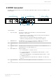


Table Of Contents

Item Interface Description
1 Input LED
•
Green: Active signal on the selected input.
•
Red: No active input signal.
•
Off: No encoding mode selected.
2 Audio LED
•
Green: Audio data is detected on the input.
•
Red: Whenever a cyclic redundancy check (CRC) error is detected, the LED
is on for five seconds.
•
Off: No audio data is detected on the input.
3 Sync LED
•
Green: The device is synchronized to the primary clock source.
•
Yellow: The device is synchronized to a secondary clock source.
•
Off: The device is not synchronized.
4 Error LED
•
Not used.
5 Control screen
•
Displays the input type and the encoding mode.
•
From the menu, you can set/view device IP addresses.
6 Navigation keys
•
Used to navigate through the device menu and to set the device IP
addresses.
7 Volume control knob
•
Not used.
8 Headphone jack
•
Not used.
9 Dim button
•
Not used.
10 Two USB 2.0 ports
•
Used to load firmware upgrades.
11 Power button
•
Powers up the unit. Use at the end of the initial installation, and for
shutting down or power cycling the device.
•
Short press: The OS shuts down correctly, closing processes and
saving open files.
•
Long press: Forces power down of the system. Nothing is saved, and
data may be lost.
12 Reset button
•
Physical reset of the device. No data is saved.
13 Over-temperature
indicator
•
Solid red: Indicates that the unit temperature is higher than the
recommended range for safe operation. Ensure that the unit front and
rear air vents are not blocked, and that the ambient room temperature
meets device environmental specifications.
•
Flashing red: Indicates fan failure.
14 Power supply failure
indicator
•
Red: Indicates that one of the power supplies has failed, or is
disconnected from the power mains.
DP591 front panel
Dolby DP591 Audio Encoder Quick Start Guide
20 August 2018 2