
Manual

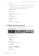

Table Of Contents
- Contents
- 1 Introduction to Dolby Object Authoring Tool DP590 documentation
- 2 Overview of Dolby Object Authoring Tool DP590
- 3 Installation of Dolby Object Authoring Tool DP590
- 4 Dolby Object Authoring Tool DP590 operation
- 4.1 Creating new or opening existing session
- 4.2 Saving session
- 4.3 Adding beds and dynamic objects
- 4.4 Modifying input channel routing
- 4.5 Enabling beds and dynamic objects for presentations
- 4.6 Setting production renderers
- 4.7 GPIO configuration
- 4.8 Monitoring local output
- 4.9 Monitoring loudness value
- 4.10 Monitoring 5.1-channel downmix
- 4.11 Monitoring dynamic range control
- 4.12 Monitoring audio meters
- 4.13 Connecting to DP591
- 4.14 Sending metadata to DP591
- 5 Error log
- Glossary

•
Sync LED:
•
Green indicates that the unit is synchronized with a source of the highest available
priority.
•
Yellow indicates that the unit is synchronized with a non-highest-priority source.
•
Off indicates that the unit is not synchronized with any source.
•
Error LED (nonfunctional)
•
User-control screen
•
Navigation keys
•
Volume control knob (nonfunctional)
•
Headphone jack
•
Dim button (nonfunctional)
•
Power failure indicator
•
Over-temperature indicator
•
Reset button
•
Power button
•
Two Universal Serial Bus (USB) 2.0 ports
2.3 DP590 rear-panel components
The rear-panel components of the DP590 provide several types of inputs and outputs.
The rear panel includes the components shown in this image.
Figure 2: DP590 rear panel
The DP590 rear-panel components are as follows:
•
Two AC power connectors
•
MADI or AES IN port
•
Gigabit Ethernet port (not in use)
•
MADI OUT port
•
Four AES OUT ports
•
Video IN port
•
Two serial digital interface (SDI) IN ports
•
Two SDI OUT ports
•
Four USB 2.0 ports
•
Gigabit Ethernet port (COMMAND)
•
Gigabit Ethernet port (MEDIA; not in use)
•
VGA video port
•
Serial port (not in use)
Overview of Dolby Object Authoring Tool DP590
Dolby Object Authoring Tool DP590 quick-start guide
Preliminary 10 May 2017 9