
- Dolby Multichannel Audio Tool User's Manual


36 Dolby
®
DP570 Multichannel Audio Tool User’s Manual
Using the DP570 Features
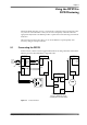
4.13 Using an External Shaft Encoder to Control Master Volume
ThemastervolumefunctionisavailableonDP570sthathavetheCat.No.548Analog
OutputCardinstalled.The
GPI/Oporthasthreepinsthatallowcontrolofmastervolume
remotelybyusingashaftencoder.Table 4‐5describestheinterface.
Table 4‐6describestheelectricalcharacteristics.
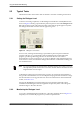
4.14 Emulator Bypass
WhenyouenableEmulatorBypass,thefront‐panelEscbuttonisilluminated.Inthis
mode,theonlysettingsthataffecttheoutputaretheroutersettings.Monitoringoptions
arelimitedtoprogramselection.Ifyouareusingthe
Lt/Rt Input,thatsignalissent,without
decoding,totheLeftandRightemulatoroutputs.Bassmanagementremainsactive.
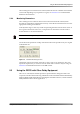
4.15 Solo Input Mode
TheDP570providesatwo‐channelanaloginputthatcanberoutedtotheanalogoutputs.
Thisinputiscalled
Solobecausethefeatureprovidesawaytorouteastandardsignalfrom
amixer(suchasthemixer’ssolobusoutput)intothemonitorchain.Thefeaturecanalso
beusefulasageneral‐purposeanalogbypass.
SoloInputmodebypassesthedigitalaudioinputs,andonlythesoloinputs
fromthe
Analog I/O connectoronthebackpanelroutetotheLeftandRightoutputs.IftheMono
speakeroutputisselected,theinputsignalsaresummedandfedtothe
Monooutput.
The
SoloinputisavailableonlybydrivingtheSoloControllineontheGPI/Oport.TheSolo
Controlline(pin6)islevel‐triggeredandisactiveinthehighstate.Thestatusofthe
Solo
inputdisplaysonthefront‐panel
SoloLEDandisindicatedontheSoloTallyline(pin5)
onthe
GPI/Oport.
4.16 Unity Gain Mode
UnityGainmodedefeatstheaudibleeffectsofdialoguenormalizationwhileallowingthe
dialnormvaluetobeusedinchoosingdynamicrangecontrolsettings.Itisvaluablewhen
theemulatoroutputsoftheDP570arereturnedtotheconsoleforuseasmonitorinputs.
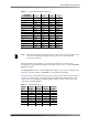
Table 4-5 Shaft Decoder Signal Descriptions
Signal Pin Description
Shaft121Shaftencoderinput.Twosquarewavesinaquadraturephaserelationship:
Shaft0leadsShaft1by90°:volumeincreases.
Shaft0lagsShaft1by90°:volumedecreases.
Shaft020
ShaftPresent 22 Groundthispintoactivatecontrolviashaftencoder.Pulledhighinternally
(10kto+5V).
Table 4-6 Shaft Decoder Signal Electrical Characteristics
Characteristic Min Max
VT+Positive‐goinginputthresholdvoltage 1.2V2.1V
VT–Negative‐goinginputthresholdvoltage 0.5V1.4V
VHHysteresisvoltage 0.4V1.5V