
User manual


A-5
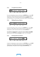
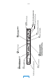
A.2.3 Back-to-Back Testing
For purposes of testing the Model DP503 and Model DP524 in a back-to-back
configuration, a special cable must be constructed. Note that a DTE to DTE
connection is not supported by the RS-449 specification; a standard 37-wire cable
cannot be used to connect the units together. The special cable connects the TT
outputs of the DP503 directly to the ST inputs of the DP503, and to the RT inputs
of the DP524. This cable also connects the SD outputs of the DP503 to the RD
inputs of the DP524, and connects the signal grounds (SG) of the two units. One
end of the cable should be labeled as Encoder (DP503), and the other as Decoder
(DP524.
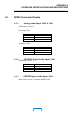
From Pin Connection To Pin Connection
DP503 4 SD+ DP524 6 RD+
DP503 22 SD- DP524 24 RD-
DP503 5* ST+ DP524 8 RT+
DP503 17* TT+ DP524 8 RT+
DP503 23** ST- DP524 26 RT-
DP503 35** TT- DP524 26 RT-
DP524 19 SG DP524 19 SG
DP524 1 shield DP524 n/c
*For convenience, tie pins 5 & 17 together in the connector shell at the
encoder. Run one line to decoder pin 8.
**For convenience, tie pins 23 & 35 together in the connector shell at the
encoder. Run one line to decoder pin 26.
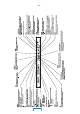
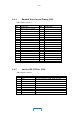
A.2.4 Dolby Fax Cable Pinout, Part No. 83293
A Dolby Fax installation requires the use of a supplied “Y” cable, two of whose
ends are terminated in 37-pin female connectors and which are labeled “encoder”
and “decoder;” and a third end terminated in a 44-pin male connector. Pinouts and
wire colors are as follows:
From Pin To Pin Connection Color
DP503 4 VSX 29 SD+ brn
DP503 22 VSX 30 SD- wht
DP503 5 VSX 42 ST+ red
DP503 23 VSX 41 ST- grn
DP503 19 VSX 1 shield blk
DP524 6 VSX 40 RD+ brn
DP524 24 VSX 39 RD- wht
DP524 8 VSX 37 RT+ red
DP524 26 VSX 38 RT- grn
DP524 19 VSX 1 shield blk
VSX 20 VSX 28 RX/Sel gra
MAIN