
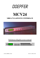
Instruction Manual
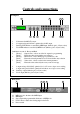

Controls and connections
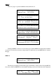
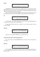
Frontpanel
1
2
3 4
5 6 7 8 9
10 11
1 32 character backlit LCD screen.
2 12 outputs using an 8-bit DAC optimised for 0~10V output
3 Start/Stop LED indicator controlled by MIDI input. (linked to pin 1 of Sync socket)
4 Clock LED indicator controlled by MIDI clock. (linked to pin 3 of Sync socket)
Dual function controls - Rotary and Push
5 {Rotary} - Output select - selects one of the 24 outputs for programming
{Push} - Enters the value selected with rotary selection
6 {Rotary} - Menu select - selects which page of parameters to edit
{Push} - Enters the selected parameter for use selected with rotary selection
7 {Rotary} - Value select - selects a value for the current parameter
{Push} - Enters the value selected by the rotary control for useage
8 4 outputs using a 12-bit DAC optimised for -2~8V at one volt per octave scaling
9 8 outputs using an 8-bit DAC optimised for 0~10v at one volt per octave scaling
10 Start/Stop output. (linked to pin 1 of Sync socket)
11 Clock output (linked to pin 3 of Sync socket)
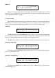
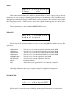
Back panel
12 MIDI out is also the thru of the MIDI input
13 MIDI input
14 Sync output with programmable divide ratio of MIDI clock
15 LCD Contrast - adjusts the viewing angle for the LCD
16 Power switch
12 13 14 15
16