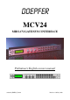
DOEPFER MCV24 MIDI-CV/GATE/SYNC INTERFACE Preliminary English owners manual written by EMIS (C) 1999 Revision 1.
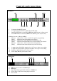
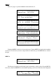
Controls and connections Frontpanel 1 2 5 1 2 3 4 6 7 8 3 4 9 10 11 32 character backlit LCD screen. 12 outputs using an 8-bit DAC optimised for 0~10V output Start/Stop LED indicator controlled by MIDI input. (linked to pin 1 of Sync socket) Clock LED indicator controlled by MIDI clock.
MCV24 Overview The MCV24 is a flexible MIDI to analogue interface, and any of it’s 24 outputs can be configured for any purpose such as control voltages for VCO pitch, control voltages for any modulation destination (such as VCF or VCA), triggers or gates. Outputs 1 to 4 are higher precision 12-bit DAC’s, whilst the rest are 8-bit DAC’s, outputs 1 to 12 are optimised for one volt per octave scaling, but can also be set to Hertz/volt scaling (like most Korg and Yamaha instruments).
MCV24 Basics The MCV24 doesn’t really have any controls for operation, once it has been programmed to do a particular function, that is exactly what it does, so once programmed, changing presets is probably the only operation required on the MCV24. However, a full understanding of what the MCV24 will do and how to set it up is a vital element that must be learned first.
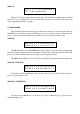
MENUS There are 7 pages of operation within the menu, labelled A to G. A- - - - - > : O u t p u t 0 1 Do e p f e r M C V 2 4 : O u t p u t 0 1 CV P a r a m e t e r <- C - - - > : O u t p u t 0 1 LF O & A D S R P a r a m <- - D - - > : O u t p u t 0 1 Mo d u l a t i o n M a t r i X <- - - E - > : O u t p u t 0 1 Sy s t e m P a r a m e t e r <- - - - F > : O u t p u t 0 1 Gl o b a l S y n c P a r .
MENU-B : O u t p u t 0 1 CV P a r a m e t e r There are two CV’s per output which are mixed together, CV1 and CV2 have different options available with some cross over, though CV1 is the only one that can be assigned notes, and CV2 is the only one that can be assigned pitch bender for example. CV PARAMETER The CV Parameter menu holds many pages, as this section is where most of the settings live.
MIDI CHANNEL Ed i t C V 1 : O u t p u t 0 1 Mi d i c h a n n e l : 0 0 1 The MIDI CHANNEL pages allows the MIDI channel to be assigned to control a particular output CV. Any channel between 1 and 16 can be selected here. In the example shown, output CV number 1 is being controlled by MIDI channel 1.
NOTE FROM Ed i t C V 1 : O u t p u t 0 1 Fr o m : C 3 This setting can be a bit difficult to grasp, yet simple when understood. This setting of FROM and the next setting of TO, allows a keyboard zone to be specified, essential a low note (From) and a high note (To) that the output CV will work within. Most of the time, this will be set across the entire keyboard, with a FROM setting of C3 (value = 000) and a TO setting of g6 (value = 127).
FROM Ed i t C V 1 : O u t p u t 0 1 Fr o m : M o d u l a t i o n The FROM and TO (next item) parameters select which controller to use. It is possible by using the FROM and TO range to specify just one controller number (perhaps this is the normal mode anyway), or a range can be specified - this could allow several controllers to control the same destination, such as Mod wheel (controller 1) and breath controller (Controller 2).
SLEW Ed i t C V 1 : O u t p u t 0 1 Sl e w :On >> This is where the Slew function is enabled or disabled. When on, the CV output voltage is slewed, which means it’s rate of change is slightly lagged, this improves the limitation of the 7-bit MIDI system, although for note information a longer setting would be used for portamento. (The slew time setting is under the CV2 parameters later on). With controllers, aftertouch and pitch bender, a greater smoothness can be achieved using slew.
VELOCITY SLEW TIME Ve l o c i : O u t p u t 0 1 Ve l S l e w T i m e : O f f If the velocity has been switched on, then this parameter allows the time for the slew.
MIDI TO (CV2) Ed i t C V 2 : O u t p u t 0 1 Mi d i t o : x x x x x x x This is the second CV routing, and is similar to CV1 functions, except that the destination options are a little different. The MIDI To function selects which MIDI event will be assigned to control the selected output (Output 01 in the case of the example shown here). Depending on which event is selected, determines how many edit pages are available, as all unrelated options are suppressed to keep things clearer.
Maximum CV output from CV2 with Scale settings Scale CV2 output 24 .............. 1v 48 .............. 2v 72 .............. 3v 96 .............. 4v 120 ............ 5v 144 ............ 6v 168 ............ 7v 192 ............ 8v 216 ............ 9v 240 ............ 10v 255 ............ 10.6v Scale CV2 output 36 ..............1.5v 60 ..............2.5v 84 ..............3.5v 108 ............4.5v 132 ............5.5v 156 ............6.5v 180 ............7.5v 204 ............8.5v 228 ............9.5v 252 ......
MENU C (LFO & ADSR PARAMETERS) <-C--- - > : O u t p u t 0 1 LF O & A D S R P a r a m This menu controls the internal LFO and envelope generators per output. LFO FUNCTION LF O :Output01 fu n c t i o n : O n >> This switches the LFO on or off for the selected output. When switched on the following parameters are available. When switched off, the LFO parameter menu is suppressed.
LFO FREQUENCY FINE (LFO Sync = Intern) LF O :Output01 Fr e q ( f i n e ):008 When the LFO Sync is set to Internal, this parameter controls the fine speed of the LFO. Each value relates to 0.01Hz (1/10 Hz), so in the example shown above, the speed is 0.08Hz, which is added to the previous parameter Frequency Coarse. The range is form 000 to 099. In the previous example here was shown a Frequency Coarse of 006, and a Frequency Fine of 008, this therefore gives an LFO speed of 6.8Hz.
LFO RATIO LF O :Output01 Ra t i o ( % ) : 5 0 The LFO Ratio controls the shape of the basic LFO waveform. A central value of 50% keeps the waveform symmetrical, so the Tri/Saw waveform is a pure Triangle, and the Rectangle wave is a pure square wave. With the Rectangle wave, the Ratio value is the pulse width, ranging for 1% to 99%. With the Tri/Saw waveform, a Ratio of 1% provides a Saw Down waveform, and a value of 99% is a Saw Up waveform as shown below.
LFO OFFSET FINE LF O :Output01 Of f s e t ( f i n e ) : 0 5 0 The LFO offset fine allows the LFO offset to be finely adjusted to a precision of 1/10 per value set. So, each setting here relates to 1/10 of the Offset Coarse. The range is 000 to 099. ADSR FUNCTION AD S R :Output01 fu n c t i o n : O n >> This switches the ADSR Envelope on or off for the selected output. When switched on the following parameters are available. When switched off, the ADSR parameter menu is suppressed.
ADSR SUSTAIN LEVEL AD S R :Output01 Su s t a i n : 0 5 0 This sets the Sustain level for the ADSR envelope generator. The range is from 000 (lowest) to 127 (highest). ADSR RELEASE TIME AD S R :Output01 Re l e a s e : 0 0 3 This sets the Release time for the ADSR envelope generator. The range is from 000 (quickest) to 127 (longest). ADSR MODULATION DEPTH AD S R :Output01 Mo d u l a . D e p t h : 1 2 7 The ADSR Modulation Depth controls the amount of ADSR modulation applied to the output.
MIDI SOURCE Mi d i E v 1 : O u t p u t 0 1 is : C o n t r o l l e r Selects the source for the modulation. The options are Controllers, Mono aftertouch, Pitch Bend and Poly Aftertouch. Midi Events 2 ~ 6 are the same as Midi Event 1 parameters. MIDI EVENT MIDI CHANNEL Mi d i E v 1 : O u t p u t 0 1 Mi d i c h a n n e l : 0 0 1 Selects the Midi channel of the modulation source. Note that each of the 6 modulation routings each have their own Midi channel.
SYSTEM PARAMETERS <- - - E - > : O u t p u t 0 1 Sy s t e m P a r a m e t e r The System Parameters are where various system setups are done, this includes calibration of the CV scaling along with renaming the outputs for easier reference. EDIT NAME Ed i t Na m e :Output01 :A100rack Each of the 24 outputs can be renamed to something that resembles your system for easier use.
TUNE CV#1 COARSE Tu n e :Output01 CV # 1 / C o a r s e : + 0 0 0 Sets the coarse voltage to CV1. TUNE CV#1 FINE Tu n e :Output01 CV # 1 / f i n e :000 Sets the fine voltage to CV1 TUNE NOTE #2 Tu n e :Output01 No t e # 2 : 0 9 6 This sets the reference Midi note number for calibration of the CV. The range is from 0 to 127. TUNE CV#2 COARSE Tu n e :Output01 CV # 2 / C o a r s e : + 1 0 2 Sets the coarse voltage to CV2.
TRIGGER LEVEL ON Tr i g g e r : O u t p u t 0 1 Le v e l O n V %:100 Sets the output level of the trigger on signal, referenced as a percentage of maximum (10.6v for outputs 13 ~ 24). So 50% would generate a 5.3V trigger. For V-Trig applications (positive gate like Doepfer A-100 and most others) use high percentage for Trigger Level on, and for S-Trig applications (like Moog) use a Trigger On Level of 0%.
SYNC POLARITY Sy n c - C l o c k Po l a r i t y : P o s i t i v Inverts the polarity of the clock output on the front panel, and the signal at the Sync DIN output on the rear panel. Normal setting is Positive. Range of settings is Positive or Negative. PRESET & UTILITIES <- - - - - -G:Ou t p u t 0 1 Pr e s e t & U t i l i t i e s This section is where the remaining system control setting are.
SEND EDIT BUFFER Se n d E d i t b./ P r e s Sy s E x - > : E d i t b u f . Transmits the current edit buffer or selected preset via MIDI system exclusive. Use the Value knob to select the Edit Buffer or any Preset memory, and then press the Value knob to transmit the data. The display will show a series of moving dots to show transmission is taking place, followed by READY ! when completed. COPY OUTPUT DATA Co p y to :Output01 :Output02 Enables any output assignment to be copied to any other output.
PARAMETER Name VALUE Output xx (the number of the output being edited) MiditoCV1 NoEvent MiditoCV2 NoEvent Midi Channel 1 Mode High Note From 0 To 127 Base 0 Slew 1/2 Off Slewtime Off Velocity Mode No Trigger Mode No Retrigger Time 0 Scale CV2 255 LFO Off ADSR Off LFO-Wave Rectangle LFO Sync Internal LFO Frequency 1.0 (Coarse/Fine) LFO Ratio 50% LFO Modulation Depth 0 LFO Offset 0.