DOEPFER MIDI Master Keyboard LMK4+ User's Guide
User's Guide LMK4+ INDEX 1. 1.1 1.2 1.3 1.4 1.5 Operation (Hardware) Power Supply MIDI-Interface Connection of External Controllers and Footswitches Controls Operating and Security Instructions 2. 2.1 2.2 2.3 2.3.1 2.3.2 2.3.3 2.3.4 2.3.5 2.3.6 2.3.7 2.3.
1. OPERATION (Hardware) 1.1 Power Supply The LMK4+ does not have a built-in power supply. Instead it uses a plug-in type external power supply (AC adapter). One reason for this feature is electrical safety. Keeping danger voltages (main) out of the keyboard increases the electrical safety. Therefore a external power supply of high quality and safety should be used. If the keyboard is used in Germany the external power supply must be VDE approved.
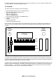
For details regarding assignment of MIDI functions to the foot controllers (e.g. volume, sustain, soft pedal and so on) refer to chapter 2.3.5 Controller Assign / Activate. 1.
1.5 Operating and Safety Instructions Please follow the given instructions for use of the instrument because this will guarantee correct instrument operation. Due to the fact that these instructions touch on Product Liability, it is absolutely imperative that they be read carefully. Any claim for defect will be rejected if one or more of the items was observed. Disregard of the instructions can endanger warranty.
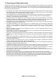
2. OPERATION (Software) 2.1 Switching the Keyboard ON When the keyboard is switched ON a message regarding the software version will appear on the display for several seconds (e.g. "LMK4 V1.00"). In addition the LED's will flicker for several seconds. After that the keyboard will go into preset-mode (see below for details) and will call up preset no. 1. NOTE: When the keyboard is activated for the very first time, the presets will contain random values since the RAM contains random data.
4: SPLIT The LMK4+ handles up to 8 different keyboard areas (split areas, split zones, split range) simultaneously. Overlaps of the zones are possible (i.e. some keys are used by more than one zone). Each zone is assigned a MIDI channel and to one of the 2 MIDI outputs. The SPLIT-menu is used to define the parameters of each of the 8 keyboard zones.
2.3 DETAILED DESCRIPTION OF MENUS 2.3.1 Preset (1) This menu is entered by pressing the leftmost MENU-button. Switching the keyboard ON will also activate this menu. It serves to call up and store presets. A preset is the sum of all information defining a keyboard configuration. All data about the 8 keyboard zones (i.e.
Storing a Preset The data of the work-memory can be stored via the PRESET-menu. It can be placed in one of the 128 preset-memory locations by pressing the PRESET-menu-key and the PANIC-menu-key (first and last menubutton) simultaneously. The following message appears on the display: STORE MODE OK? Also, all 8 LED's will be illuminated as a warning! Next the desired BANK-button and possibly the PRESET-menubutton (to alter the range 0...64/65...128) to be pressed, followed by a NUMBER-button.
Same as item 1, except that only a single preset is being overwritten. After receiving the single dump the data are stored in the volatile memory (RAM) of the LMK4+. A external Store message must follow the dump to transfer the data to the non-volatile memory. Alternatively a manual memory transfer has to be carried out (see chapter 3.3.7). If an error is detected during the transmission ("Checksum error"), it is immediately interrupted and every second LED flashes as a visual indication of an error.
devices connected to LMK4+ if the bank message is supported and which values for Controller #0/32 are used. Normally only a few combinations of controller #0 and #32 are allowed to select one of the program banks availabe. Some manufacturers also use only Controller #0 or #32 to select a program bank. Other manufacturers designate this function as page, page select or variation.
YYYYYYY is one of the following 4 choices that can be adjusted together with the MIDI-master-channel XX via the rotary encoder: POUT1&2 POUT1&0 POUT0&2 OUT1&2 external Preset call-up active / Outputs 1&2 external Preset call-up active / Output 1 external Preset call-up active / Output 2 external Preset call-up turned off / Output 1&2 In case of POUT... (first 3 choices) the Preset call-up via incoming MIDI Program-Change messages on the Master-channel is active.
In the submenu CHANNEL the MIDI-channel, the source and the MIDI-outputs for the zone are adjusted. By repeated pressing of the submenu button (= number button 3) the following combination can be selected: XX / O: Y&Z XX is the source for the zone. Y and Z represent the MIDI-outputs 1 and 2 on which the MIDI messages of the zone in question are passed through..
If the display shows the message "STORE" on the upper right when the PROGRAM/BANK-button is pressed, then the function in question is presently activated. This means that the program-number and bank-numbers entered will be stored in the preset and will be sent when the preset is called up (see Menu 1: PRESET). If this is not desired in a given keyboard zone, then the function can be disabled by pressing the PROGRAM/BANK-button once more.
2.3.5 Controller Assign/Activate (5) This menu is selected by pressing the fifth MENU-button from the left. The menu has 2 functions. The first is the assignment of controllers to the standard MIDI-functions ("Assign"- function). The second is the activation of the controllers in the various keyboard zones ("Activate"-function). When entering this menu one reaches the "Activate"-portion first. The following message appears on the display: ZONE : 00Y CONTR.
The following standard MIDI-functions can be assigned to the various controllers (with abbreviations): Pitch Bend Portamento Aftertouch Data Entry Modulation Volume Breadth-Controller Panorama PIT POR ATO ENT MOD VOL BRE PAN In addition there are 8 user-defined controllers (UD1...UD8) which are explained in section 2.3.6. The assignment of the selected controller to a MIDI-function is accomplished by turning the data-entry dial.
A special case is the assignment of of the after-touch-sensor to pitch-bend. There is a global parameter in menu 7 (PARAMETERS), called ATP (Aftertouch-to-Pitch) which determines whether the pressure exerted on the keys has a positive or negative effect on pitch-bend. Without pressure the pitch-bend value of 64 is sent ($40 Hexadecimal). If ATP is positive, increasing pressure on the keys causes the pitch-bend values 64...127 ($40...$7F Hex) to be sent; a negative ATP results in values 64...0 ($40...
the preset presently active (see CONTROLLER ASSIGN/ACTIVATE for details). When the switch is pressed the following message will appear on the display: LINK TO PRES > YYY YYY is the number of the next preset activated when presets are switched over. The number is set to the desired value via the data-entry dial. It is also possible to form loops since there are no restrictions on the setting of the preset-pointer.
global, i.e. once set it is valid for all presets stored in the LMK4+. Of course the parameter is meaningful only if the aftertouch sensor has been assigned to the pitch-bend function. The last BANK-button triggers the Memory transfer from volatile to the non-volatile part after a receive dump. Before the transfer is performed the following message appears in the display: STORE ALL PRESETS TO EEPROM? Also, all 8 LED's will be illuminated as a warning! Only if the BANK-button No.
APPENDIX A: Explanation of the velocity-response curves and aftertouch curves. When defining the parameters of the keyboard zones one can select among 64 velocity-response curves and 8 aftertouch curves. In the following paragraph the reasons for this feature shall be discussed briefly. The special MIDI-chip used inside the LMK2 to poll the key-contacts uses the time difference required by the switch-contact to derive the velocity response (or dynamics-value).
VELOCITY-RESPONSE CURVES AFTERTOUCH-RESPONSE CURVES LMK4+ User's Guide Page 21
Appendix B: Pin Assignment of the Jack Sockets Power Supply 1 "high" end 2 "low" end 1 = +7...12V DC 2 = GND Foot Controller (EXT.CTRL. 1/2) 2...
Appendix D: Quick reference table of functions LMK4+ User's Guide Page 23
Appendix E: Initialization of the LMK4+ One must operate the two right-hand menu buttons PARAM.NAME and PANIC simultaneously for several seconds while connecting the power supply. Then the message "EEPROM-SETUP" appears in the upper line of the display. Operating the first menu button (PRESET) starts the set-up routinees and the message in the display changes to "INIT PRESETS". Operating the data entry knob changes the 3 digit display in the lower row.