DOEPFER MIDI Master Keyboard LMK2+ User's Guide
LMK2+ User's Guide INDEX 1 Power Supply 2 MIDI Connection 3 Connection of External Pedal and Foot Controller 4 Controls 5 OPERATING AND SECURITY INSTRUCTIONS 6 Operation of the Keyboard 6.1 Switching the Keyboard ON 6.2 Menu Structure 6.3 Description of Menus 6.3.1 PRESET 6.3.2 PROGRAM CHANGE/BANK/REALTIME 6.3.3 SPLIT 6.3.4 CHANNEL 6.3.5 TRANSPOSE 6.3.6 DYNAMIC 6.3.7 CONTROLLERS 6.3.
1. POWER SUPPLY The LMK2+ does not have a built-in power supply. Instead it uses a plug-in type external power supply (AC adapter). One reason for this feature is electrical safety. Keeping danger voltages (main) out of the keyboard increases the electrical safety. Therefore a external power supply of high quality and safety should be used. If the keyboard is used in Germany the external power supply must be VDE approved.
. CONTROLS The LMK2+ features the following controls and displays: • • • • • 3-digit LED display 8 MENU-buttons in 2 rows of 4 buttons each 8 LEDs (serving as indicators for the MENU-buttons) 1 Wheel without spring (assignable to any MIDI Controller #1..31) 1 spring loaded Wheel (for Pitch Bend function) In addition LMK2+ is equipped with a monophonic After Touch sensor below the keys that is activated if you put pressure on the keys pressed down.
6. OPERATION OF THE KEYBOARD 6.1 SWITCHING THE KEYBOARD ON When the keyboard is switched ON a message regarding the software version will appear for several seconds on the display (for example "100" for version 1.00) and the LEDs will flicker for several seconds. After that the keyboard will go into the PLAY-mode and all settings made before turning the keyboard off previously are automatically called up (non volatile memory for the last settings).
5 TRANSPOSE In this menu the transpositions of the 4 keyboard zones are set. 6 DYNAMIC In this menu the velocity-response curves for the 4 keyboard zones are set. 16 different velocity tables are available. 7 CONTROLLER In this menu the on/off status of each wheel, the after touch sensor, the external foot switches and the external foot controller is determined for each keyboard zone, as well as the controller number (#1...31) for the first wheel (the not spring loaded type).
6.3 DETAILED DESCRIPTION OF MENUS The following rules apply to all menus and will not be mentioned in each individual menu description: • A menu is activated by pressing the corresponding MENU-button. The active menu is indicated by an illuminated LED. • In some cases, menus are deactivated automatically once certain parameters have been set. The keyboard will then go into PLAY-mode. Other menus can be exited only by pressing another MENU-button.
6.3.1 PRESET (1) Leftmost button in the upper row The PRESET-menu serves to call up the user preset (1) or one of the 16 factory presets (2-17). Each preset contains all data about the 4 keyboard zones, i.e. the corresponding keyboard ranges, MIDI-channels, transpositions, allocation and activation of the controllers and the velocity-response curves. When entering this menu the LED display will show the number of the currently selected preset.
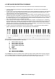
Sending a realtime instruction The upper three white keys of the lowest octave are assigned to the real time instructions START (G), STOP (A), and CONTINUE (H). If one of these three keys is pressed while beeing in menu 2 the corresponding realtime instruction is sent. An abbreviation of the message will appear on the display for several seconds ("StP", "StA", "CON"), then the keyboard goes into PLAY-mode. Pay attention that LMK2+ transmits only these three real time events. No clock events i.e.
6.3.7 CONTROLLER (7) Third button in the lower row This menu serves to activate or deactivate the wheels, the after touch, the external footswitches and the external foot controller in the 4 keyboard zones. Additionaly the controller number for the wheel without spring is determined in this menu. When entering this menu the number of the currently selected keyboard zone is shown on the left side of the display, on the right side on of the following abbreviations is to be seen: Abbrev.
Appendix A: Information about the velocity-response curves When defining the parameters of the keyboard zones, one can select among 8 velocity-response curves. In the following paragraph the reasons for this feature shall be discussed briefly. The special MIDI-chip used inside the LMK2+ to poll the key-contacts uses the time difference required by the switch-contact to derive the velocity response (or dynamics-value).
Appendix B: Pin Assignment of the Jack Sockets Power Supply 1 "high" end 2 1 = +7...12V DC 2 = GND "low" end Foot Controller ("Volume") 2...
Appendix C : Velocity-Response Reduction Factor for the Black Keys Because of the shorter leverage the black keys have a slightly higher velocity response than the white keys with pressure being equal. The LMK2+ enables to reduce the velocity values of the black keys in comparison to the white keys. To adjust the reduction factor you have to keep pressed the first button (PRESET) during power on. In this case you will enter a special menu where a 3 digit number is to be seen on the display.