
Manual

doepfer
System A - 100
VC Waveform Processor A-116
3
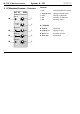
3. Controls
1 Lev.
The
input amplifier
’s gain can be set with attenuator
1. Since the gain amount is variable from 0 up to a
factor of 2, you can attenuate as well as amplify input
signals.
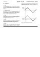
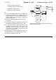
2 Clipping Level
With control
2
, you set the
clipping threshold
level
in a range from -10 V to +10 V. Any part of a
waveform which was
above
this threshold is clipped -
that is, held at the threshold level (see Fig.1).
3 CCV
If you want to use a CV at input " to control or
modulate the clipping threshold, set the clipping con-
trol voltage level
with Attenuator
3
.
4
SCV
Symmetry can likewise be controlled or modulated by
voltage control. Use attenuator 4 to control the
level of the symmetry control voltage at input
§
.
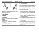
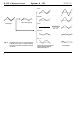
5 Sym.
Symmetry, that is the g
ain factor of the internal
symmetry VCAs, is altered by control 5. The Sym-
metry VCA is a special amplifier which operates in the
amplification range from -1 to +1, so can amplify
negative as well as positive voltages (see Fig. 2).
Fig. 1: how the clipping level works
0
Clipping
Level
0
Clipping
Level