
User guide


A-109
VC Signal Processor
System A - 100
doepfer
10
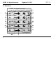
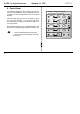
6. Patch-Sheet
The following diagram of the modules can help you
recall your own Patches. They’re designed so that a
complete 19” rack of modules will fit onto an A4 sheet
of paper.
Photocopy this page, and cut out the pictures of this
and your other modules. You can then stick them
onto another piece of paper, and create a diagram of
your own system.
Make multiple copies of your composite diagram, and
use them for remembering good patches and set-ups.
P
• Draw in patchleads with colored pens.
• Draw or write control settings in the little
white circles.
A-109
VC Signal Processor
24 dB Low Pass / VCA / Panning
CV F2
0
10
0
10
0
10
0
10
0
10
0
10
0
10
0
10
0
10
CV F1
CVQ2 CVQ1
CVA 2 CVA 1
CV P2 CVP1
Audio In 2 Audio In 1
(to V CF Audio Input)
Level
Pan Out L Pan Out R
Pan In
VCA Out
VCA In
VCF Out
CV F1
CVQ1
CVA1
CV P1
Frq.
Res.
Amp.
Pan.
VCF
VCA
PAN